
Method of yawing a rotor of a wind turbine

a wind turbine and rotor technology, applied in the direction of motors, engine control, proportional algorithms, etc., can solve problems such as yaw errors, and achieve the effects of reducing the maximum load that a wind turbine should withstand, lightening the weight of wind turbine components, and increasing the yaw speed of a rotor

Active Publication Date: 2019-02-12
VESTAS WIND SYST AS
View PDF20 Cites 1 Cited by
  • Summary
  • Abstract
  • Description
  • Claims
  • Application Information

AI Technical Summary

Benefits of technology

The invention provides a method for yawing a wind turbine rotor at a faster speed to reduce yaw error, which is the deviation of the rotor's axis from the wind direction. This method helps to reduce the loads that the wind turbine needs to withstand, making it lighter and cheaper. The cost of each wind turbine blade is estimated to be reduced by 15% and the overall cost of energy is estimated to be reduced by 3.1%. The method also reduces or eliminates the need for extreme flap moment protection alarms. The preferred motor used for increasing the yaw speed is an electric motor.

Problems solved by technology

Yaw error is an amount an axis about which the rotor is rotatable is not parallel to wind direction to which the rotor is exposed.

Method used


Image

  • Method of yawing a rotor of a wind turbine
  • Method of yawing a rotor of a wind turbine
  • Method of yawing a rotor of a wind turbine

Examples


Embodiment Construction

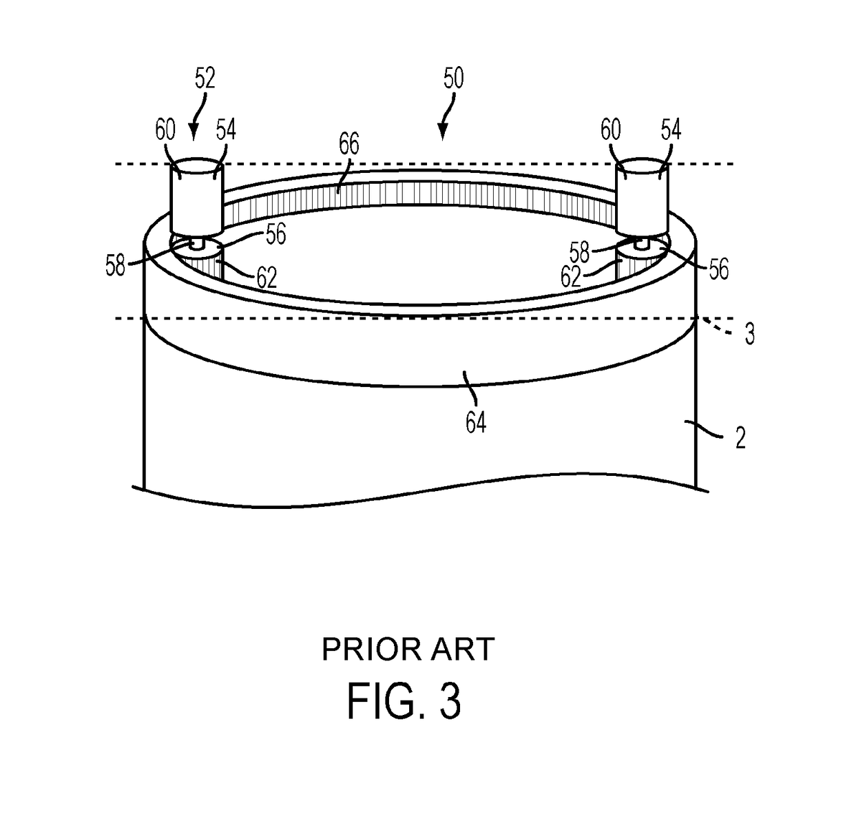
[0031]FIG. 4 illustrates an example controller 100 for an upwind wind turbine 1 for controlling or implementing a method for controlling a yaw system of the wind turbine 1, such as that of FIG. 3.

[0032]The controller 100 includes means for implementing the method comprising a memory 102 and a processor 104. The method implemented on the processor may be implemented in hardware or software. The processor 104 has an input 106 for the direction the rotor 4 faces and an input for the wind direction 108 to which the wind turbine 1 is exposed. The direction the rotor 4 faces is measured through sensors (not shown) located around the yaw ring 64 in a known arrangement. The wind direction is measured by a wind vane (not shown), which is a known arrangement. The processor 104 is in communication connection with memory 102 via connection 110. The controller 100 is in communication connection via connection 112 with the motors 54. The wind direction may also be measured by a LIDAR device (Ligh...


PUM


Abstract

A wind turbine (1) in which the yaw speed of a rotor (4) of the wind turbine (1) is increased, in a direction to reduce yaw error, from a first speed to a faster second speed when at least one of a yaw error threshold and a rate of change in yaw error threshold is exceeded. Yaw error is an amount an axis about which the rotor (4) is rotatable is offset from the wind direction to which the rotor (4) is exposed. As a result, the maximum loads that a wind turbine 1 should withstand may be reduced and lighter wind turbine components result.

Description

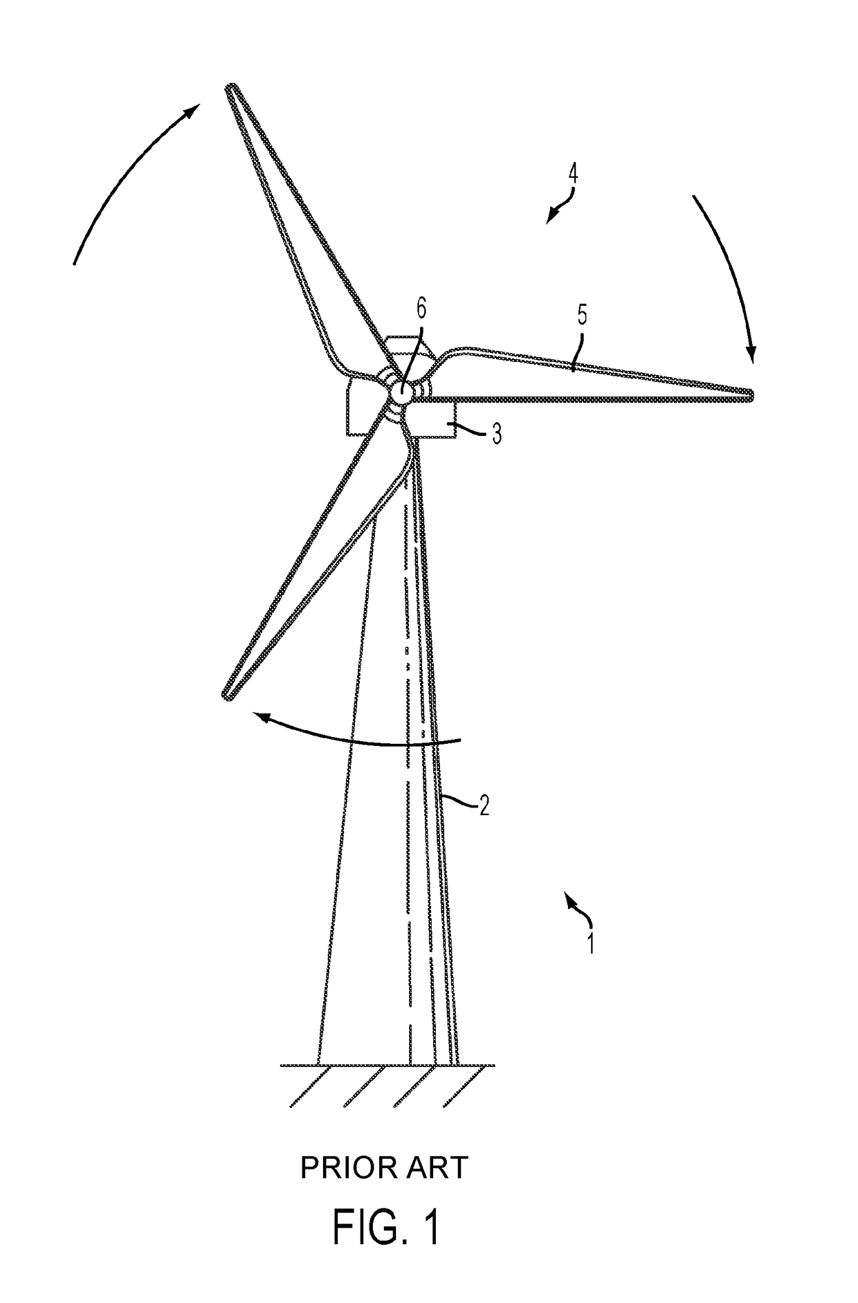
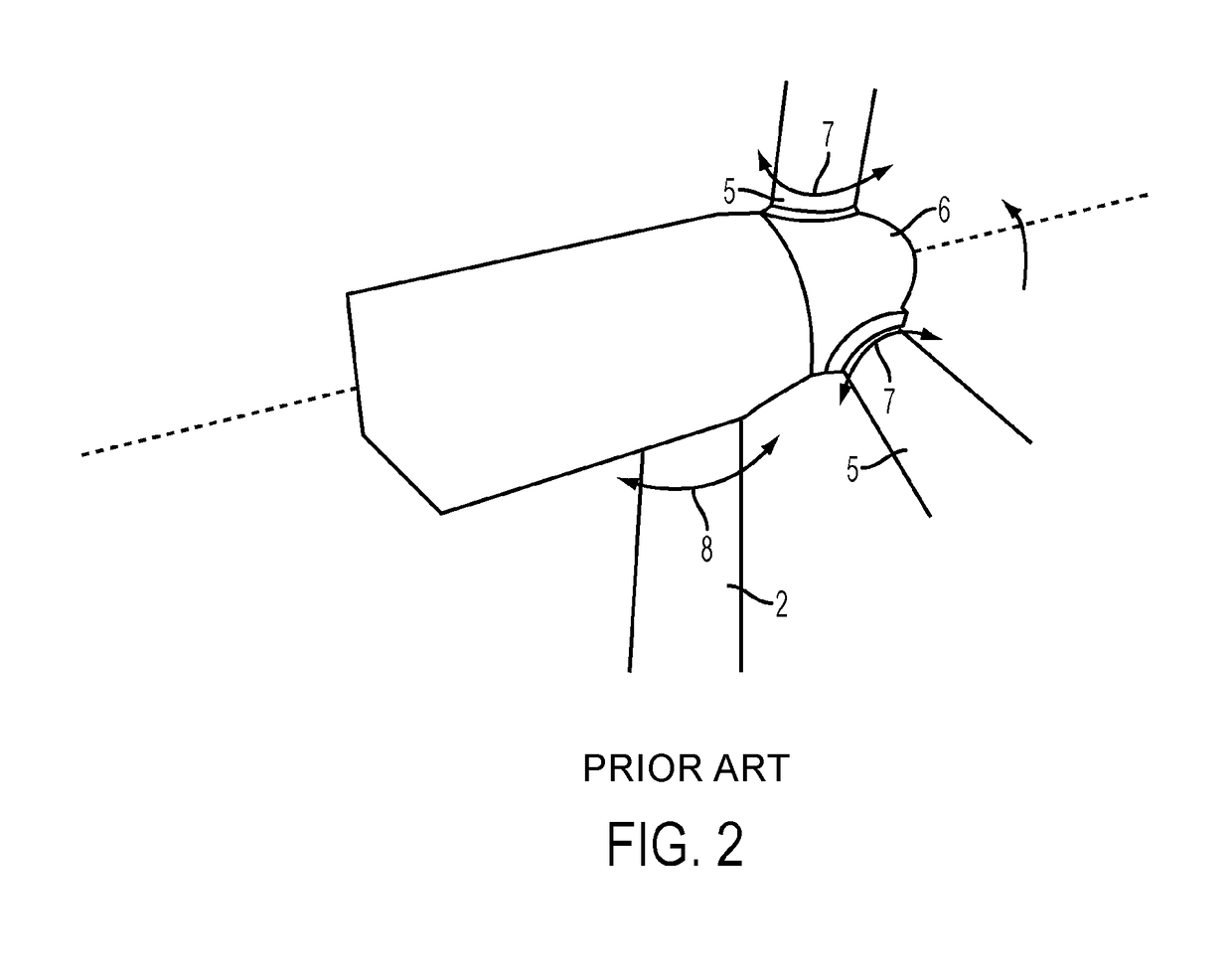
BACKGROUND OF THE INVENTION[0001]The invention relates to a wind turbine, and in particular a method of yawing a rotor of a wind turbine.[0002]A typical known wind turbine 1 is illustrated in FIGS. 1 and 2. It comprises a wind turbine tower 2 on which a wind turbine nacelle 3 is mounted. A wind turbine rotor 4 comprising wind turbine blades 5 is mounted on a hub 6. The hub 6 is connected to the nacelle 3 through a low speed shaft (not shown) extending from the nacelle front. The low speed shaft is connected to a gearbox that drives a high speed shaft and the high speed shaft drives a generator (not shown). In large wind turbines suitable for use in large scale electricity generation on a wind farm, for example, the diameter of the rotor can be as large as 100 meters or more and the mass of the nacelle, blades and hub on top of the tower is considerable and can be a few hundred tons or more. The rotor rotates about a rotational axis shown by the dashed line.[0003]The example wind tur...

Claims


Application Information

Patent Timeline
Patent Type & Authority Patents(United States)
IPC IPC(8): F03D7/04F03D7/02
CPCF03D7/0204F03D7/042F05B2270/309Y02E10/723F05B2270/329F05B2270/701F05B2270/321Y02E10/72
Inventor SPRUCE, CHRIS
Owner VESTAS WIND SYST AS
Learn More