Supercharge Your Innovation With Domain-Expert AI Agents!

Coherent optical receiver

a receiver and optical technology, applied in the direction of electromagnetic transmission, electrical equipment, transmission, etc., can solve the problems of relatively complex signal processing, large power consumption and expansive digital signal processors, etc., and achieve the effect of minimizing or maximizing the strength of the first dithering signal

Active Publication Date: 2019-02-12
NOKIA SOLUTIONS & NETWORKS OY
View PDF9 Cites 8 Cited by
  • Summary
  • Abstract
  • Description
  • Claims
  • Application Information

AI Technical Summary

Benefits of technology

The present patent is about a method and apparatus for coherent demodulation of quadrature-modulated (QM) light. The technical effects of this patent include improved demodulation of QM light by providing an offset in one of the I-channel and Q-channel signals and using optical quadrature heterodyne detection to extract the HF tones from the two electrical signals. The apparatus can also be used to receive polarization multiplexed (PM) light and detect the distinct dither signal therein. The control circuit can vary the control signal to minimize or maximize the strength of the first dither signal and align the two light signals to transmitter polarization channels.

Problems solved by technology

This signal processing may be relatively complex and thus typically require relatively power-consuming and expansive digital signal processors.
Accordingly, it may be understood that there may be significant problems and shortcomings associated with current solutions and technologies for demodulating optical quadrature modulated signals.

Method used


Image

  • Coherent optical receiver
  • Coherent optical receiver
  • Coherent optical receiver

Examples


Embodiment Construction

[0022]In the following description, for purposes of explanation and not limitation, specific details are set forth, such as particular optical circuits, circuit components, techniques, etc. in order to provide a thorough understanding of the present invention. However, it will be apparent to one skilled in the art that the present invention may be practiced in other embodiments that depart from these specific details. In other instances, detailed descriptions of well-known methods, devices, and circuits are omitted so as not to obscure the description of the present invention. All statements herein reciting principles, aspects, and embodiments of the invention, as well as specific examples thereof, are intended to encompass both structural and functional equivalents thereof. Additionally, it is intended that such equivalents include both currently known equivalents as well as equivalents developed in the future, i.e., any elements developed that perform the same function, regardless...


PUM


Abstract

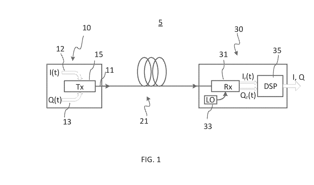
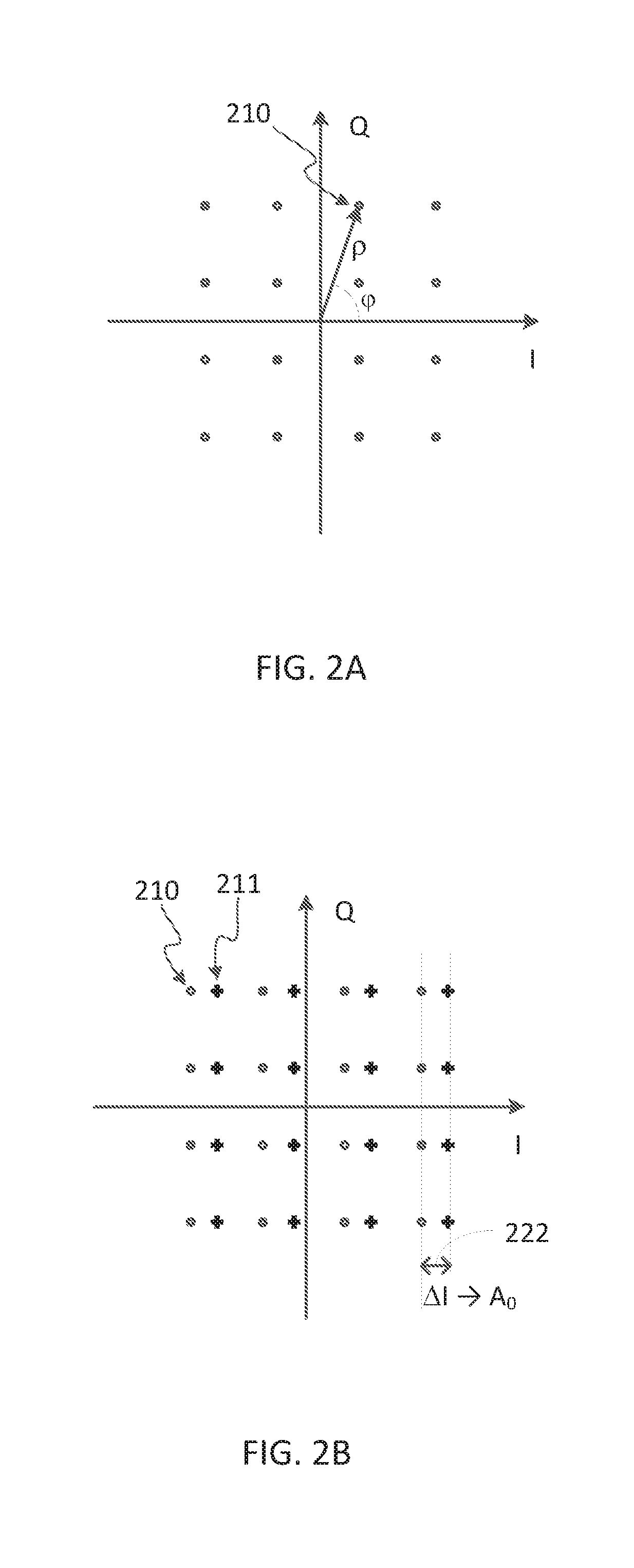
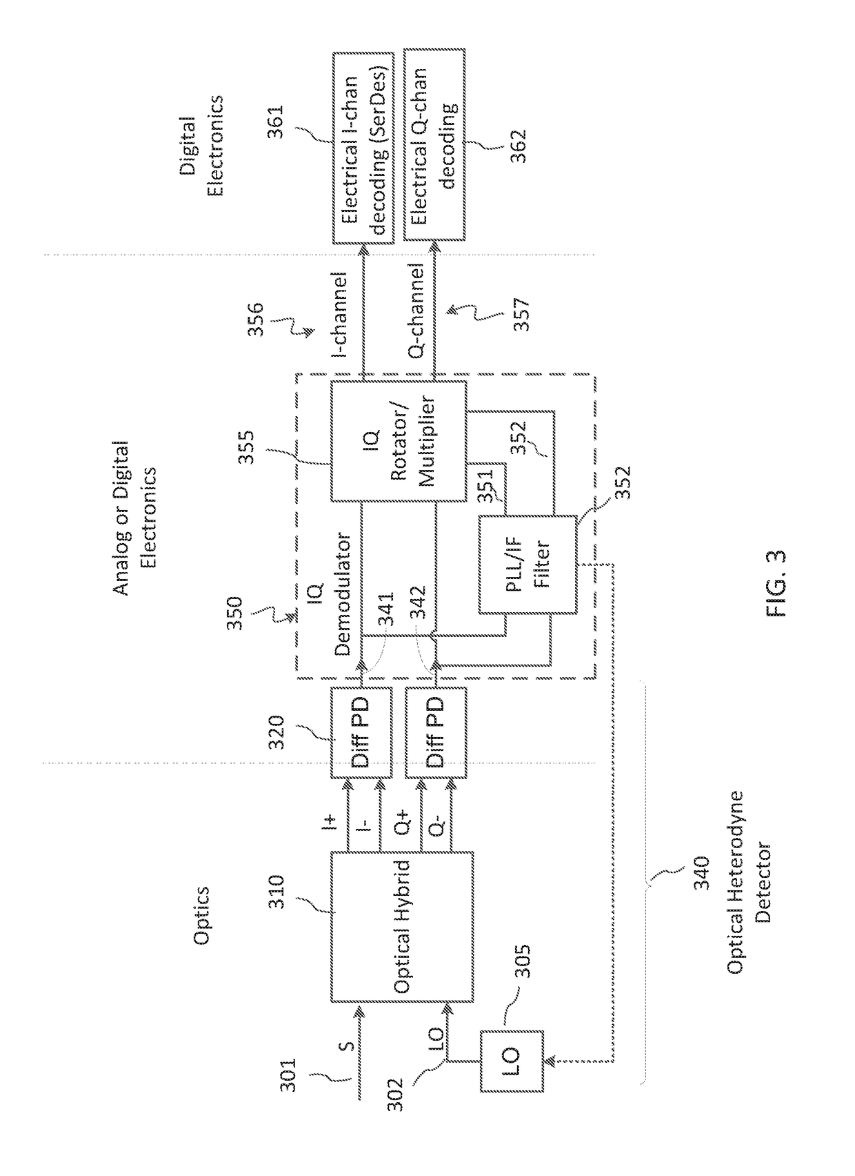
An optical IQ demodulator that does not require a power-consuming DSP is disclosed. A DC offset is added to one of the I and Q optical signal components at an IQ transmitter. After mixing with an LO signal and differential detection at the receiver, this DC offset results in a heterodyne-frequency tone in each of the quadrature detection channels of the receiver. The phase of this oscillation is recovered using a PLL circuit, which output is used to separate the transmitter I and Q channels for decoding thereof using conventional electronics.

Description

FIELD OF THE INVENTION[0001]The invention generally relates to coherent optical receivers, and more particularly relates to an apparatus and method for demodulating optical quadrature modulated signals.BACKGROUND OF THE INVENTION[0002]Optical waveguide modulators used in high-speed optical communications. such as those based on waveguide Mach-Zehnder (MZ) interferometric structures, may require active control of their operating conditions, and in particular of their bias voltage that sets the relative phase of interfering light waves in the modulator in the absence of the modulation signal. The waveguides of the modulator are typically formed in an electro-optic material, for example a suitable semiconductor or LiNbO3, where optical properties of the waveguide may be controlled by applying a voltage. Such a waveguide modulator may be a part of an optical integrated circuit (PIC) implemented in an opto-electronic chip.[0003]Very high speed optical systems may benefit from one of quad...

Claims


Application Information

Patent Timeline
IPC IPC(8): H04B10/64H04J14/06
CPCH04B10/64H04J14/06H04B10/6165H04B10/6166
Inventor BAEHR-JONES, THOMAS WETTELAND
Owner NOKIA SOLUTIONS & NETWORKS OY
Features
  • R&D
  • Intellectual Property
  • Life Sciences
  • Materials
  • Tech Scout
  • Unparalleled Data Quality
  • Higher Quality Content
  • 60% Fewer Hallucinations
Learn More