
Supporting structure for supporting sealed cartridges, transport or packaging container and process for processing the same

a technology for supporting structures and sealed cartridges, which is applied in the field of batch processing of sealed cartridges, can solve problems such as damage to filling nozzles, glass cartridges may get broken, and damaged filling nozzles, and achieve the effect of improving the supporting structure and efficient processing of cartridges

Active Publication Date: 2019-02-19
SCHOTT POONAWALLA PVT LTD
View PDF19 Cites 13 Cited by
  • Summary
  • Abstract
  • Description
  • Claims
  • Application Information

AI Technical Summary

Benefits of technology

The present invention provides an improved supporting structure for holding multiple sealed cartridges. This structure ensures that there is a proper height difference between processing station members (such as filling nozzles) and the cartridges, which allows for efficient processing. The invention also includes a transport or packaging container for holding this supporting structure. This improves the handling and transportation of the sealed cartridges.

Problems solved by technology

There is one tub and nest format available in the market for pre-crimped cartridges but there are lots of disadvantages to use this existing tube and nest format with existing as well as new filling and stoppering machines because this tub and nest format requires complete setting change from infeed to outfeed for accommodating different height level of cartridge into the nest.
Further the drawback of two different change parts needs separate validation study as per GMP (Good Manufacturing Practice) guidelines requirements.
If one tries to fill the pre-crimped cartridge nest available in the market on the same machine without changing the machine height setting accidents will happen which may cause damage to the filling nozzles or glass cartridges may get broken because the height difference between the filling nozzles and the pre-crimped cartridges is too small.
These disadvantages similarly hold 1) for manual filling and stoppering machines, which are operated electrically and pneumatically and where the processes are triggered by an operator, 2) for semi automatic filling and stoppering machines, which are operated electrically, electronically and pneumatically and where the operator has to remove the outer bag of the tub and nest assembly and then a top lid from the tub along with an inner sheet, and 3) for fully automatic filling and stoppering machines, which are operated electrically, electronically and pneumatically and where whole packets are inserted into the filling and stoppering machine one by one, the machine will automatically remove the outer bag and then remove the top lid from the tub by means of an automatic peeling off unit, then the inner sheet of the tub and nest assembly will be removed automatically and the machine will then automatically pick up the nests by means of a vacuum cup and place them onto transport carriers, which are then moved towards the filling station nozzles for the medicine filling process.
If the tub and nest assemblies available in the market are directly fed for filling of pre-crimped cartridges on the same machine without any alterations in the filling machines then the filling nozzles can be damaged or glass cartridges can be broken because the height difference between the filling nozzles and the pre-crimped cartridges is too small.
All the above activities will incur higher costs and also additional time will be required to change the parts resulting in production losses.
Further all fully automatic machines and new separate change parts are very expensive.
Also this nest can only be used for cylindrical pharmaceutical containers, such as vials or cylindrical ampoules, that have no retaining edges like the hand rests of conventional syringe bodies.

Method used


Image

  • Supporting structure for supporting sealed cartridges, transport or packaging container and process for processing the same
  • Supporting structure for supporting sealed cartridges, transport or packaging container and process for processing the same
  • Supporting structure for supporting sealed cartridges, transport or packaging container and process for processing the same

Examples


Embodiment Construction

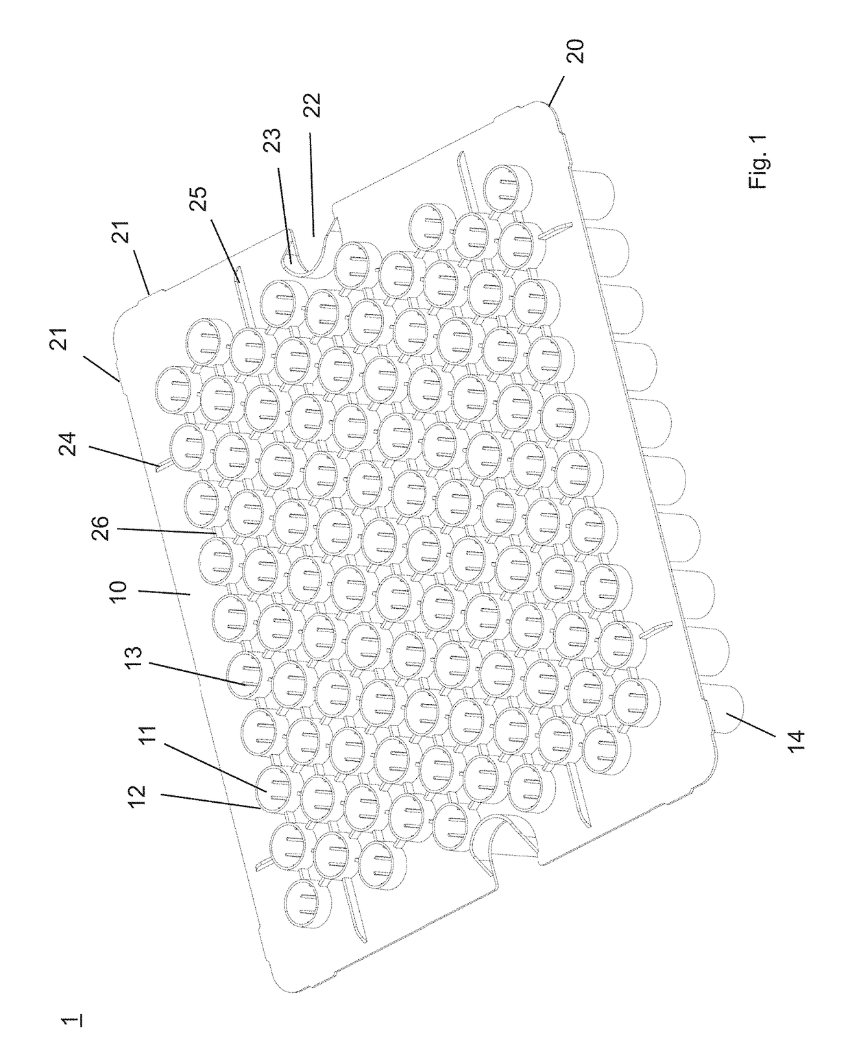
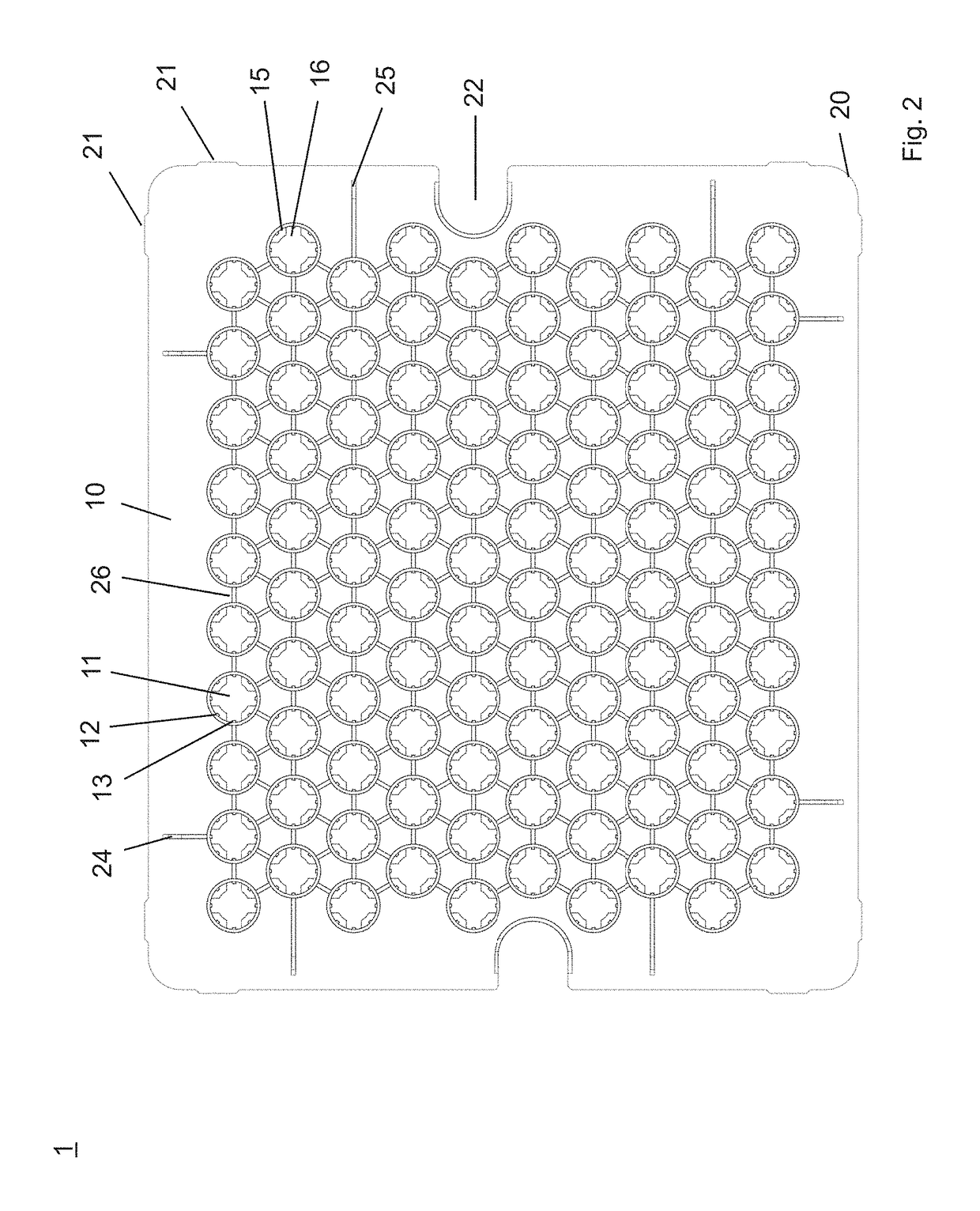
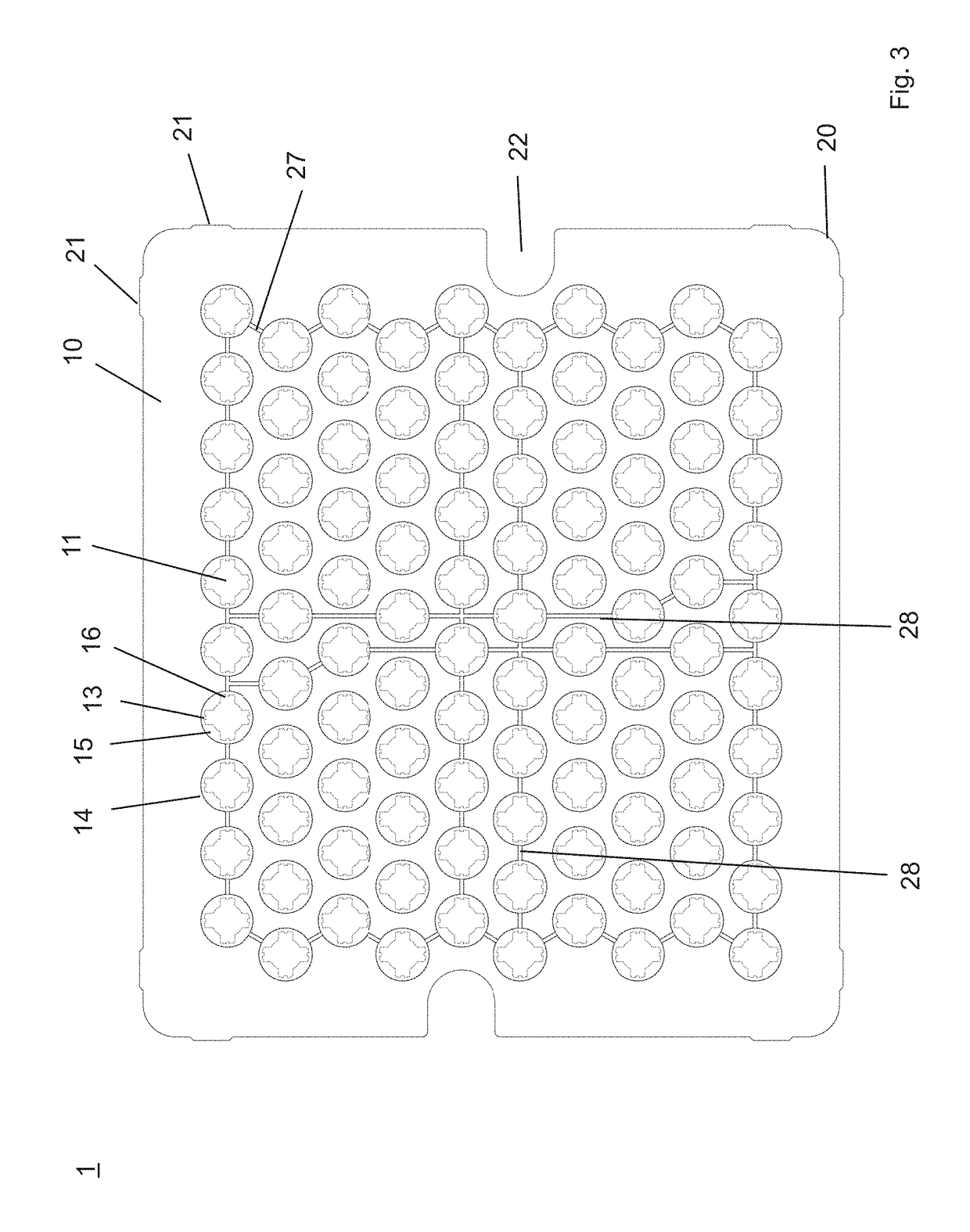
[0045]A supporting structure (in the following nest) in the sense of the present invention is used for concurrently supporting a plurality of sealed cartridges for use in pharmaceutical, medical or cosmetic applications. Such cartridges, including pen cartridges, by-pass cartridges and dental cartridges, are a commonly-used packaging solution for drug delivery systems, e.g. insulin administration, pen systems, pump systems, auto-injectors and needle free injectors. For special requirements such as by-pass and chemically strengthened cartridges, personalized designs are available on the market. Cartridges available on the market may be made of glass material, particularly of Fiolax® glass from SCHOTT AG, and offer fixed volumes for drug delivery of e.g. 1.0 ml, 1.5 ml and 3.0 ml. Different volumes usually correspond to different axial lengths of the cartridges.

[0046]An example for such a cartridge embodied as a syringe barrel is shown in FIG. 6 and comprises an upper end with a filli...


PUM


Abstract

A supporting structure for supporting a plurality of sealed medical cartridges is disclosed, comprising a planar supporting plate having a plurality of receptacles for accommodating the sealed cartridges. Retaining protrusions are formed at the bottom ends of the receptacles protruding inward, which are mated with the shoulder portions of the sealed cartridges in such a manner that the shoulder portions of the sealed cartridges are supported on the retaining protrusions of the receptacles and that the upper ends of the sealed cartridges protrude from the upper ends of the receptacles at an upper side of the planar supporting plate, when the sealed cartridges are accommodated upside-down in the receptacles. The inventive nest will be suitable for any nested liquid filling machine without much changes in filling table and general settings.

Description

[0001]The present application is a U.S. National Stage Application based on and claiming benefit and priority under 35 U.S.C. § 371 of International Application No. PCT / IN2015 / 000394, filed 16 Oct. 2015, which in turn claims benefit of and priority to Indian Application No. 1590 / MUM / 2015 filed 17 Apr. 2015, the entirety of both of which is hereby incorporated herein by reference.FIELD OF INVENTION[0002]The present invention relates in general to the processing of a batch of sealed cartridges, particularly of pre-crimped cartridges, for use in pharmaceutical, medical or cosmetic applications and relates in particular to a supporting structure (also named nest) provided for holding sealed or pre-crimped cartridges for filling and stoppering operation. Further aspects of the present invention relate to a nest and tub assembly accommodating sealed cartridges, which can be directly fed on existing filling and stoppering machine set-ups for processing sealed prefillable syringe barrels.BA...

Claims


Application Information

Patent Timeline
Patent Type & Authority Patents(United States)
IPC IPC(8): B65D1/34A61M5/00B65B31/02B65B3/00B01L3/00B01L9/06A61J1/06A61J1/14B65B7/28B65B43/59B65B43/54B65B55/04B65B55/20B65B61/20B65B7/16B65B39/00
CPCB65B61/207A61J1/062B65B7/161A61J1/1412A61M5/008B01L3/5082B01L3/523B01L9/06B65B3/003B65B7/2821B65B31/027B65B39/00B65B43/54B65B43/59B65B55/04B65B55/20B01L2200/185B01L2300/042B01L2300/044B01L2300/0835B01L2300/123B65B2039/009B65D77/04
Inventor NARVEKAR, ANIL NARAYANPOTDAR, PRATUL PRAKASHDADACHANJI, RISHAD KAIRUS
Owner SCHOTT POONAWALLA PVT LTD
Learn More