Automated test equipment for testing a device under test and method for testing a device under test

a technology of automatic testing equipment and test equipment, which is applied in the direction of automated testing systems, instruments, error detection/correction, etc., can solve the problems of increasing the cost of electrical energy, increasing the cost of operation, and reducing the competitiveness of test floors containing many ate, so as to achieve the effect of reducing power consumption

Active Publication Date: 2019-03-19
ADVANTEST CORP
View PDF11 Cites 1 Cited by
  • Summary
  • Abstract
  • Description
  • Claims
  • Application Information

AI Technical Summary

Benefits of technology

[0012]It has been found by the inventors that a more power-efficient concept for testing a device under test can be provided when an automated test equipment for testing such device under test comprises a control unit which is configured to put resources which are currently not needed (on which there is currently no demand) in a state of lower activity when compared to a state of higher activity in which such a tester subunit is in conventional systems typically operated, even if there is currently no demand for such a tester subunit. Hence, the inventors have found that it is advantageous to put tester subunits which are currently not needed in a state of lower activity in which these tester subunits typically consume less current than in a state of higher activity. By putting tester subunits which are currently not used or not needed (e.g. for performing a certain test on the device under test) into a state of lower activity a current consumption of these tester subunits can be dramatically reduced without losing any functionality of the automated test equipment.
[0015]By having the automated detection of the utilization of the tester subunits and by automatically putting tester subunits into a lower state of activity or into a higher state of activity (e.g. when the tester subunits are currently needed) the test program can be free of any instruction, which instructs the control unit to put one or more of the plurality of tester subunits into the state of lower activity. Hence, the responsible user who creates the test program does not have to take care of the reduction of power consumption of the tester subunits by manually placing unneeded tester subunits into as state of lower activity, as this is already performed automatically by the control unit of the automated test equipment while running the test program. Furthermore, existing test programs which are programmed for conventional automatic test equipment don't have to be changed to benefit from the new automatic test equipment as the control unit can automatically derive the utilization of the tester subunits from the test program and put the tester subunits into the state of lower activity which are currently not needed or not used.
[0019]According to further embodiments, a further way of ensuring that only tester subunits are used for performing a test on the device under test is that the control unit is configured to scan the test program for an upcoming tester subunit utilization and to put a tester subunit, which, when being in the state of lower activity went out of its specification limit, into the state of higher activity before this tester subunit is needed for performing an instruction of the test program, such that when the instruction is to be performed afterwards this tester subunit is already back in its specification limns. In other words, the control unit can be configured to scan the test program in advance for an upcoming resource utilization and can put tester subunits which need a certain amount of time to get back in their specification limits into the state of higher activity already before the tester subunits are needed such that, when the tester subunits are needed afterwards, they are already in their specification limits. This has the advantage that the control unit does not have to pause the test program and to wait until a tester subunit, which was in a state of lower activity, is back in its specification limits.
[0020]Hence, some embodiments of the present invention relate to an automated integrated circuit tester with the particular property of having a specific power control system to lower or to minimize the power consumption during operation and in an idle state.
[0021]Furthermore, further embodiments of the present invention are also related to a method to either allow the manual user control of power consumption or to have the power consumption to be controlled automatically by the automatic test system, for example, according to user guidelines. Further embodiments of the present invention are also related to a method of generating specific information to indicate the status of a tester resource (or of a tester subunit) with respect to its accuracy specifications, which for example, may be given by the manufacturer of the automatic test equipment. Such a resource status detection (which may be understood as detection if a tester subunit is within its specification limits) can go far beyond just protecting the tester subunit from destruction by simply measuring a temperature.

Problems solved by technology

The cost of electrical energy is becoming an increasingly important portion of the overall test costs, since integrated semiconductor devices (IC) increase in speed, transistor count and system complexity with the constant achievements of modern semiconductor technology.
Such a demand is currently satisfied at the expense of a significant increase in power consumption for operating ATE and its related infrastructure.
The competitive operation of a test floor containing many ATE is only possible when the equipment can be adapted quickly to a large portfolio of devices and applications.
In the past the stability was ensured by keeping ATE powered all the time with all its resources and infrastructure fully active, resulting in a growing cost for the electrical energy supplied to the ATE.
Therefore a growing amount of energy consumption is observed for the air conditioning of the test floor buildings and the heat exchangers of global cooling units on the production plants.
This energy also contributes to a constantly growing cost of test.
Therefore it can be observed that the decision on what production equipment is used / purchased is more and more influenced by governmental programs and local legislation aiming at a transition to more environmentally compatible, but also more costly ways of producing electrical energy as well as by the higher energy taxes.
The energy capacity of the supply network is often close to the limits and overload situations can't be resolved quickly when the equipment constantly maintains its full power demand.

Method used


Image

  • Automated test equipment for testing a device under test and method for testing a device under test
  • Automated test equipment for testing a device under test and method for testing a device under test
  • Automated test equipment for testing a device under test and method for testing a device under test

Examples


Embodiment Construction

[0028]Before embodiments of the present invention are described in detail, it is to be pointed out that the same or functionally equivalent elements are provided with the same reference numbers and that a repeated description of elements having the same reference numbers is omitted. Hence, descriptions provided for elements having the same reference numbers are mutually exchangeable.

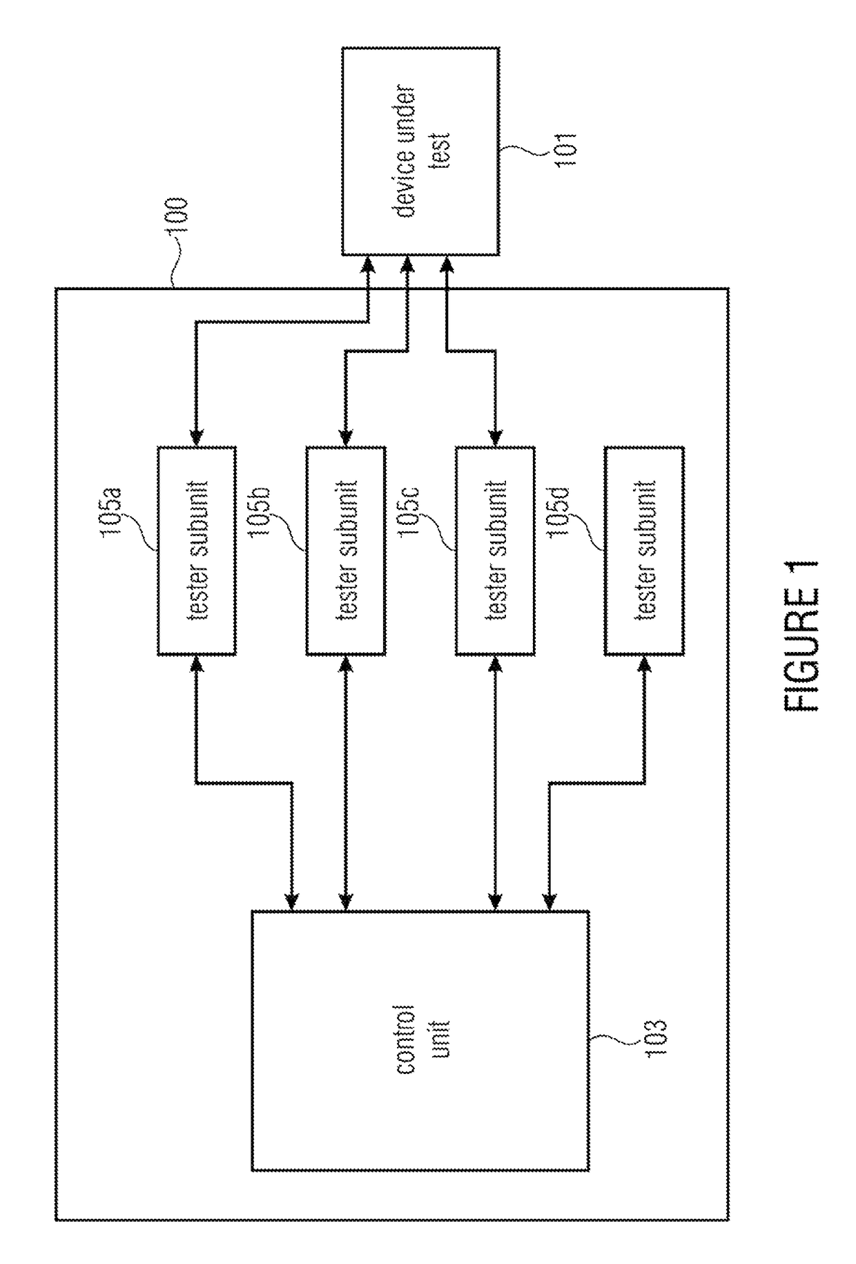
[0029]FIG. 1 shows a block schematic diagram of an automated test equipment 100 (ATE 100) for testing a device under test 101 according to an embodiment of the present invention.

[0030]The automated test equipment 100 comprises a control unit 10 and a plurality of tester subunits 105a-105d. Although in the example shown in FIG. 1 the automated test equipment 100 comprises four tester subunits 105a-105d, this number of tester subunits may be arbitrary and may depend on the purpose of the automated test equipment 100. Furthermore, although in the example shown in FIG. 1 the automated test equipment 100 is o...


PUM


Abstract

An automated test equipment for testing a device under test includes a control unit and a plurality of tester subunits. The control unit is configured to put the tester subunits in a state of lower activity in dependence on a current demand on the test resources.

Description

CROSS-REFERENCE TO RELATED APPLICATIONS[0001]This application is a continuation of copending International Application No. PCT / EP2013 / 067943, filed Aug. 29, 2013, which is incorporated herein by reference in its entirety.BACKGROUND OF THE INVENTION[0002]Embodiments of the present invention relate to an automated test equipment for testing a device under test. Further embodiments of the present invention relate to a method for testing a device under test.[0003]The cost of test is a critical economic aspect for semiconductor manufacturers and semiconductor test companies (test houses) and thus a key competitive value for automated test equipment (ATE). The cost of electrical energy is becoming an increasingly important portion of the overall test costs, since integrated semiconductor devices (IC) increase in speed, transistor count and system complexity with the constant achievements of modern semiconductor technology. The consequence is a similarly growing demand in speed, accuracy a...

Claims


Application Information

Patent Timeline
Patent Type & Authority Patents(United States)
IPC IPC(8): G01R31/28G01R31/3183G01R31/319G06F11/273
CPCG01R31/2834G01R31/2877G06F11/2736G01R31/318307G06F11/273G01R31/31903
Inventor HORST, JONASNUESSLE, HEINZLAQUAI, BERND
Owner ADVANTEST CORP
Why Eureka
Try Eureka