Supercharge Your Innovation With Domain-Expert AI Agents!

Method for determining depth for generating three dimensional images

a three-dimensional image and depth calculation technology, applied in image analysis, image enhancement, instruments, etc., can solve the problems of virtually impossible, laptops and tablets) to have depth calculation processed or even stored, and the available cpu of processing devices is quite a substantial amount, so as to achieve better and faster analysis of large amount of image data

Active Publication Date: 2019-03-26
INUITIVE
View PDF23 Cites 0 Cited by
  • Summary
  • Abstract
  • Description
  • Claims
  • Application Information

AI Technical Summary

Benefits of technology

This approach reduces computational load and improves processing speed by dynamically adjusting the disparity range, enhancing the detection of objects of interest while minimizing noise and resource consumption, making it feasible for consumer devices to handle stereoscopic video streams.

Problems solved by technology

This amount of information makes it virtually impossible (particularly for consumer products such as laptops and tablets) to have it processed or even stored for a short while, as to do so would require resources that are usually unavailable in consumer products, given their expected target prices.
Depth calculation under real time conditions typically consumes quite a substantial amount of the processing device's available CPU.
This process is very cumbersome and may require a considerable CPU resources or dedicated hardware, or might take a long period of time.
Also, it is known that using only a partial range of the disparity existing between the two images, might cause a problem due to the fact that features present outside of the defined range, might be considered as features that are present within the range, and clearing the false disparity values has no efficient full solution.
This method, as explained above, may provide good results but yet consumes considerable amount of system resources.

Method used


Image

  • Method for determining depth for generating three dimensional images

Examples


Embodiment Construction

[0031]In this disclosure, the term “comprising” is intended to have an open-ended meaning so that when a first element is stated as comprising a second element, the first element may also include one or more other elements that are not necessarily identified or described herein, or recited in the claims.

[0032]In the following description, for the purposes of explanation, numerous specific details are set forth in order to provide a better understanding of the present invention by way of examples. It should be apparent, however, that the present invention may be practiced without these specific details.

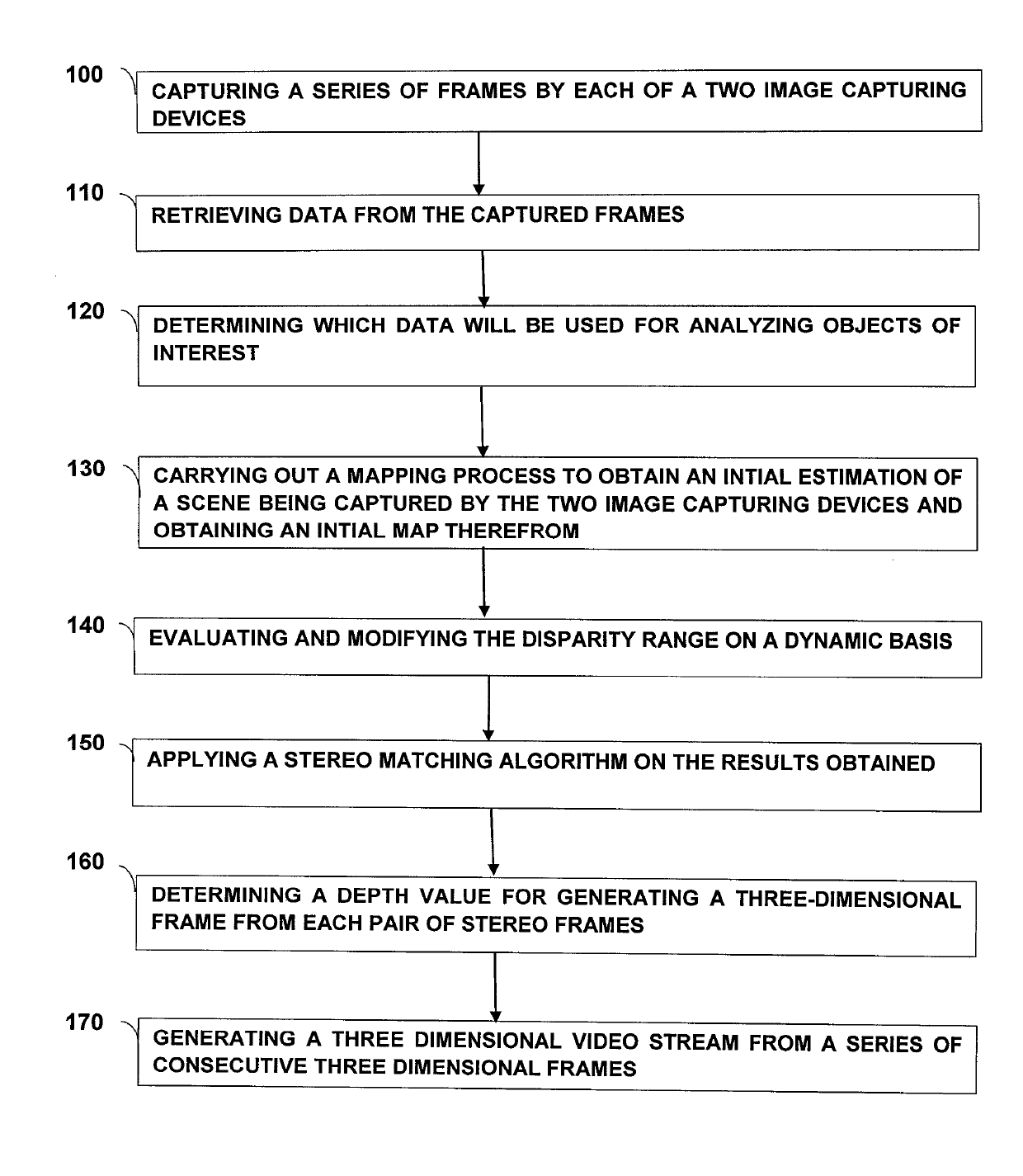
[0033]As already explained above, the method provided herein may be regarded as a method that comprises two main stages. At the initial stage, a relatively small number of images are obtained from the two or more image capturing devices. Based on data retrieved from these images, a determination is made as to data that will be used for analyzing objects of interests, or in other words,...


PUM


Abstract

A method is provided for generating a three dimensional frame. The method comprises the steps of: retrieving information that relates to a plurality of images of a target captured by two image capturing devices; determining data that will be applied for analyzing objects of interests included in the captured images; calculating disparity between groups of corresponding frames, wherein each of said groups comprises frames taken essentially simultaneously by the two image capturing devices; determining an initial estimation of a disparity range for the frames included in the groups of the corresponding frames; evaluating a disparity range value for each proceeding group based on information retrieved on a dynamic basis from frames included therein, and changing the value of said disparity range when required; and applying a current value of the disparity range in a stereo matching algorithm, and generating a three-dimensional frame for each proceeding group of corresponding frames.

Description

TECHNICAL FIELD[0001]The present disclosure generally relates to methods for using optical devices, and more particularly, to methods that enable stereoscopic reconstruction of three-dimensional images.BACKGROUND[0002]A stereoscopic camera arrangement is an apparatus made of two camera units, assembled in a stereoscopic module. Stereoscopy (also referred to as “stereoscopics” or “3D imaging”) is a technique for creating or enhancing the illusion of depth in an image by means of stereopsis. In other words, it is the impression of depth that is perceived when a scene is viewed with both eyes by someone having normal binocular vision, which is responsible for creating two slightly different images of the scene in the two eyes due to the eyes′ / camera's different locations.[0003]Combining 3D information derived from stereoscopic images, and particularly for video streams, requires search and comparison of a large number of pixels to be held for each pair of images, each of which derived ...

Claims


Application Information

Patent Timeline
Patent Type & Authority Patents(United States)
IPC IPC(8): H04N13/239G06T7/593H04N13/00H04N13/128
CPCH04N13/239G06T7/593H04N2013/0081G06T2207/20G06T2207/20228G06T2207/10021H04N13/128
Inventor BREGMAN AMITAI, ORNA
Owner INUITIVE
Features
  • R&D
  • Intellectual Property
  • Life Sciences
  • Materials
  • Tech Scout
  • Unparalleled Data Quality
  • Higher Quality Content
  • 60% Fewer Hallucinations
Learn More