Method of fabricating structures, starting from material rods

a technology of material rods and fabrication methods, applied in the direction of scanning probe techniques, instruments, optical elements, etc., can solve the problems of difficult to determine the optimal etching time, interfere with the definition of the aperture angle, and glass surface with considerable roughness, etc., and achieve the effect of low cos

Inactive Publication Date: 2019-04-16
CONSIGLIO NAT DELLE RICERCHE +1
View PDF8 Cites 0 Cited by
  • Summary
  • Abstract
  • Description
  • Claims
  • Application Information

AI Technical Summary

Benefits of technology

[0020]The Applicant has found that if the surface of the tip is too rough or is marred by other imperfections, then a subsequently applied metal coating, applied to the tip after its formation (as required in some applications of the optical fiber probes), may happen to have pinholes that interfere with the definition of the aperture angle. Irregularities can moreover become starting points for thermal degradation of the applied metal coating, thereby lowering the optical fiber damage threshold and reducing its useful lifetime and performance.
[0043]Last but not least, the method of the present invention can be practiced at very low cost.

Problems solved by technology

Also, a problem of etched tips is the sensitivity of the tip shape to the environmental influences such as vibrations, temperature drifts, etc. occurring during the etching process, which result in a glass surface with considerable roughness.
The Applicant has also found that another problem of chemical etching is that it is difficult to determine the optimal etching time.
The Applicant has found that if the surface of the tip is too rough or is marred by other imperfections, then a subsequently applied metal coating, applied to the tip after its formation (as required in some applications of the optical fiber probes), may happen to have pinholes that interfere with the definition of the aperture angle.
Irregularities can moreover become starting points for thermal degradation of the applied metal coating, thereby lowering the optical fiber damage threshold and reducing its useful lifetime and performance.

Method used


Image

  • Method of fabricating structures, starting from material rods
  • Method of fabricating structures, starting from material rods
  • Method of fabricating structures, starting from material rods

Examples


Embodiment Construction

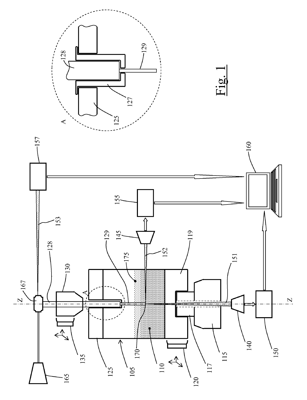
[0067]Making reference to the drawings, FIG. 1 schematically shows a set-up, according to an embodiment of the present invention, for producing structures, e.g. optical fiber probes, starting from material rods, by means of a method according to an embodiment of the present invention.

[0068]A vessel 105, e.g. a plastic cuvette, is provided to contain an etchant liquid 110, for example an aqueous solution of hydrofluoric acid (HF). The vessel 105 is associated with a drive mechanisms comprising a motor 115 (e.g. an electric motor) that, via a transmission, e.g. a shaft 117, is operable to cause the vessel 105 to rotate around a rotation axis coinciding with a vessel longitudinal (vertical) axis Z. In the example schematically shown in the drawings, the motor shaft 117 engages directly the vessel 105 at a bottom portion 119 thereof, however other types of motion transmission are possible, e.g. indirect transmissions exploiting gears or belts. A micropositioner 120 comprising a micromot...


PUM

PropertyMeasurementUnit
diameteraaaaaaaaaa
diameteraaaaaaaaaa
diameteraaaaaaaaaa

Abstract

A method, and corresponding apparatus, of fabricating a structure by chemical wet etching starting from a material rod of millimetric or sub-millemetric size, the method comprising: dipping an end portion (170) of the material rod (128,129) into a vessel (105) containing an etchant liquid (110) and a protective overlayer (175) floating on top of the etchant liquid, imparting a relative rotational movement of the etchant liquid with respect to the end portion (170) of the material rod immersed therein, wherein said imparting a relative rotational movement comprises imparting to the etchant liquid a rotational movement component with respect to a static reference system.

Description

BACKGROUND OF THE INVENTION[0001]Field of the Invention[0002]The present invention relates in general to methods of fabrication of structures starting from rods of materials by wet chemical etching. Particularly, the present invention relates to methods of fabrication of structures starting from material rods of millimetric or sub-millimetric size. Embodiments of the present invention relates to the fabrication of nanostructures, i.e. structures having al least one feature size in the nanometric range. Embodiments of the present invention relates in particular to the field of nanoprobes, particularly—although not limitatively—optical fiber probes (hereinafter also referred to as optical nanoprobes).[0003]Overview of the Related Art[0004]Optical fiber probes with small size tips (nanotips) have attracted much interest in the areas of biosensors and Scanning Near-field Optical Microscopy (SNOM)[0005]SNOM is a promising imaging technique overcoming diffraction limits. The probe used by...

Claims


Application Information

Patent Timeline
Patent Type & Authority Patents(United States)
IPC IPC(8): H01L21/67G01Q60/22C23F1/16B05C3/10B05C3/02H01L21/461C03C25/68G02B6/26
CPCC23F1/16B05C3/02B05C3/10C03C25/68H01L21/461H01L21/67075H01L21/67086G01Q60/22G02B6/262
Inventor BARUCCI, ANDREACOSI, FRANCOPELLI, STEFANORIGHINI, GIANCARLOSORIA, SILVIANUNZI CONTI, GUALTIEROGIANNETTI, AMBRA
Owner CONSIGLIO NAT DELLE RICERCHE
Why Eureka
Try Eureka