
Lower body fitness apparatus for providing enhanced muscle engagement, body stability and range of motion

a low-body, muscle-enhancing technology, applied in the direction of resilient force resistors, weights, gymnastics, etc., can solve the problems of incomplete engagement of gluteal muscles, greatest range of hip extension cannot effectively target all gluteal muscles, and optimal targeting of gluteal muscles, so as to enhance gluteal muscle engagement, body stability and range of motion, and provide safe and efficient maximum engagement of all gluteal muscles.

Inactive Publication Date: 2019-04-23
KAMINS PAUL
View PDF22 Cites 0 Cited by
  • Summary
  • Abstract
  • Description
  • Claims
  • Application Information

AI Technical Summary

Benefits of technology

The present invention is an improved lower body fitness apparatus that provides enhanced gluteal muscle engagement, body stability, and range of motion. Unlike other known cable machines, the present invention safely and efficiently provides maximal engagement of all gluteal muscles, sparing the user from undue discomfort and wasted effort. The apparatus includes a line-swiveling assembly that enables a resistance-transmitting line to swivel about a vertical swivel axis and a gripping device positioned relative to the swivel axis to allow for effective and even exercise of the entire buttocks, along with increased range of motion and continuous proper stability and body alignment. The apparatus enables a new unanticipated synergistic effect that leads to optimal gluteal muscle exercise. It allows users to work their gluteal muscles with greater efficiency, comfort, and lifts more weight and follow through with more rigorous and strength-building movement than other gluteal exercise techniques typically allow. The apparatus also ensures streamlined straight-legged exercise, which makes its basic design highly ergonomic.

Problems solved by technology

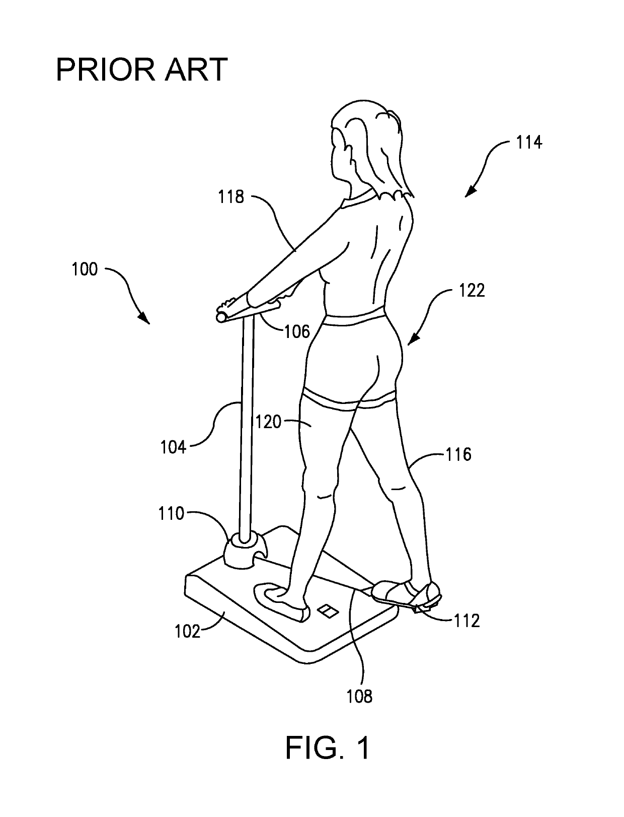
However, several limitations of this device 100 prevent optimal targeting of the gluteal muscles.
Furthermore, even the greatest range of hip extension cannot effectively target all gluteal muscles, particularly the gluteus medius and minimus.
These limitations lead to incomplete engagement of the gluteal muscles.
Exercising only the gluteus maximus produces unbalanced results.
However, this motion is not possible with the machine shown.
The resistance is generated by a spring, with limited adjustability, thereby potentially limiting the extent of pulling of the line 108.
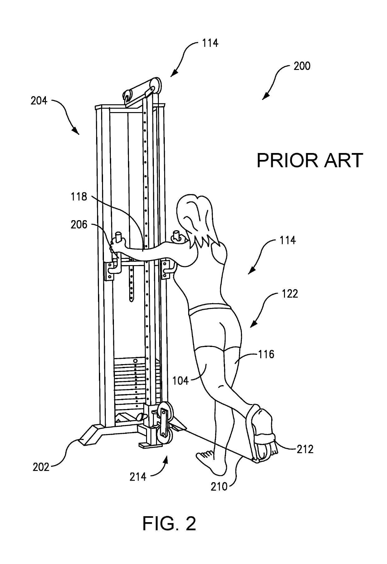
Unlike the prior art design of FIG. 1, this machine 200 does not allow a user to lean forward into the space beyond the vertical axis of the pulley's 214 swiveling action.
Without being able to lean forward, a user cannot achieve proper form during hip extension, and thus even their range of allowable hip extension motion is severely limited.
Additionally, despite the apparent improvements of this design over FIG. 1, even this device 200 enables hip abduction only in limited ways.
In addition to poor grip during abduction, the user's posture is compromised.
However, even a small displacement of the exercising leg for hip extension and / or abduction can generate resistance.
Such convenience is not made available by the line-swiveling assemblies of the prior art of FIG. 1 or FIG. 2.
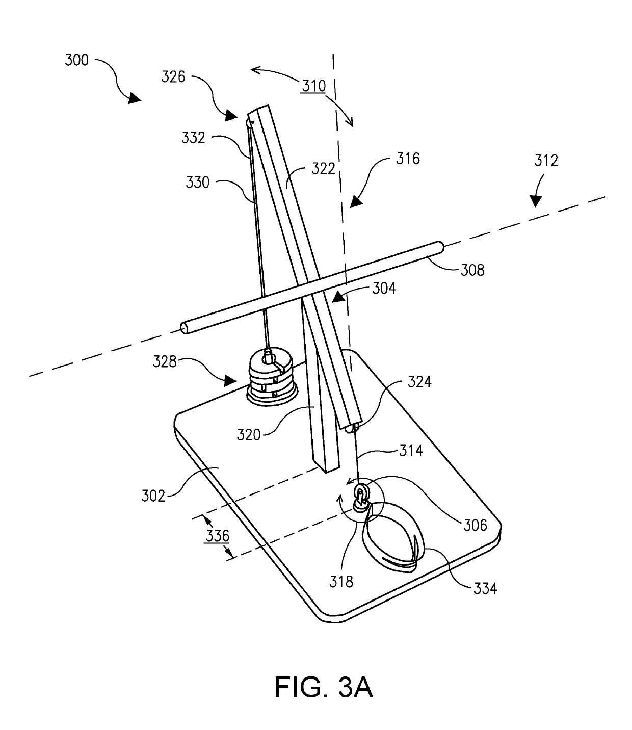
If the swivel 306 was not placed at the feet but further forward instead, then leg movement during abduction would be complicated by a forward force vector of resistance.
This would yield especial difficulty at the beginning of leg movement, when the proportion of the forward vector would be largest.
For example, in machine embodiments like the one shown in FIG. 2 where a user stands near a swiveling pulley, the design does not introduce an intermediate guiding pulley 324 at or below hip height, because such designs do not prioritize the goal of providing a user with optimal gluteal muscle targeting.
Because the generic machine of FIG. 2 attempts to accommodate many different muscle groups, its design thereby sacrifices the specific goal of gluteal muscle exercise efficiency.
Even more narrowly tailored machines still widely miss the mark, for example by failing to separate the grip and swivel axes, among other problems (see FIG. 1).
This requirement rules out the narrow grip loci of the prior art of FIGS. 1 and 2, as those grip loci would not enable the user to properly counter the significant torque that occurs particularly during leg movement comprised largely of hip abduction.
As such, the design is not optimal for gluteal work specifically.
Although ingenious in its design, the terminal pulley pair 352 which allows for both high and low use, comprise a rather bulky unit.
The lowest setting leaves the cable attachment to the LERD 334 elevated to an extent that it does not enable the LERD to sit flat for convenient resting during use.
Thus not only is it impossible for the user to routinely straddle the swivel axis 362, but they also have no chance of effecting tripod posture for any of their leg exercises.
Unfortunately, for the reasons described above, the handles do not allow for full spectrum or optimal gluteal work.
Should the user attempt to remain facing the machine, stabilizing the torso with the supplied handles in a backward stance, an anterior force vector contaminates pure abduction, and limits maximal weight recruitment.
Resting neutral, again, cannot be achieved.
And in this position, a comfortable and stable tripod type stance is not possible, the stationary limbs are all residing in the same plane.
The prior art of FIGS. 1 and 2 cannot enable straight hip abduction.
On the other hand, a user of FIG. 2 could not lean beyond the swivel axis to fully make use of the available motion in the Sagittal plane, and would sacrifice close to half their potential range of motion.
Considering the structural design of the prior art of FIG. 2, it would not be possible for a user of that machine to extend their leg back nearly as far as the user in FIG. 5B, due to the lack of a leaning space, and the higher position of its handles.
Even the prior art of FIG. 1 cannot allow for the same range of hip extension as shown in FIG. 5B, owing to the restrictive influence of its customized shoe and the poor stability afforded by its narrow grip, as well as the limited length of its cable.
Proper form has a bearing on muscle development, and yet good form can be difficult to maintain.
Poor form can strain a user's back, muscles and / or joints.
An effective tripod posture can only be achieved if the user stands back from the gripping device.
Otherwise, leg movement would be compromised and distracted by a forward-component to the force vector of resistance.
This stiffens the body, strains the back, and greatly compromises form and range of motion.
Tripod posture is indispensible to proper hip abduction, yet would not be possible without displacement of the swivel axis from the grip axis.
But even in these narrow instances, the direction and intensity of the force of resistance is more likely to be discontinuous and disrupted if the user 1200 is not straddling the swivel axis.
In all such cases, exercise is greatly compromised if the user 1200 does not assume swivel straddle stance.

Method used


Image

  • Lower body fitness apparatus for providing enhanced muscle engagement, body stability and range of motion
  • Lower body fitness apparatus for providing enhanced muscle engagement, body stability and range of motion
  • Lower body fitness apparatus for providing enhanced muscle engagement, body stability and range of motion

Examples


embodiment 600

[0152]FIG. 6 is a profile view of a possible commercial embodiment 600 of the invention, again being used to perform full hip extension. As above, this embodiment 600 includes a base 602, a frame 604 attached to and supported by the base 602, a line-swiveling assembly 606 coupled with the base 602 (via a metal tongue 603), a gripping device 608 connected to the frame 604, and a leaning space 610 that allows the user 400 to lean their upper body for full range of exercise motion during any combination of hip extension and hip abduction under resistance.

[0153]While certain elements shown here (such as the frame 604, for example) are unique to this embodiment 600, the same functional framework of FIG. 3B is present, and achieving the same benefits here as previously discussed. The structural variations of this embodiment 600 therefore do not depart from the essence of the inventive concept. Instead, those variations commingle with and enhance the effectiveness of the functional framewo...

embodiment 300

[0154]As with the earlier illustrative embodiment 300, in FIG. 6 the line-swiveling assembly 606 is a swiveling pulley configured to engage with a resistance-transmitting line 612 to enable a pullable end of the line 612 to swivel about a vertical swivel axis, thereby allowing the user 400 to pull the pullable end with an exercising leg 406 (via a lower extremity receiving device 614, or “LERD”), to perform full range of motion for any combination of hip extension and hip abduction under resistance from a single standing position. Here, an inelastic weight-bearing resistance cable 612 is being used.

[0155]From the line-swiveling assembly 606, the resistance-transmitting line 612 is guided across the frame 604 along a pathway that is laid out by a series of pulleys, discussed below. The frame 604 itself includes: a vertical support post 616 attached to the base 602; a grip support bar 618 coupled with the vertical support post 616; a conventional weightlifting frame 620 attached to th...

embodiment 700

[0164]While certain elements shown here (such as the frame 702, for example) are unique to this embodiment 700, the same functional framework of FIG. 3B is present, and achieving the same benefits here as previously discussed. The structural variations of this embodiment 700 therefore do not depart from the essence of the inventive concept. Instead, those variations commingle with and enhance the effectiveness of the functional framework, thereby asserting and demonstrating its value even more clearly.

[0165]As in the embodiment of FIG. 6, an inelastic resistance line 612 is guided across the frame via pulleys, including: the intermediate guiding pulley 624 (also sometimes called an intermediate pulley), the internal frame pulley 625 (shown in FIG. 6 but not shown here), and the pair of top frame pulleys 626. All these pulleys 624, 625, 626 function together as a resistance-activating pulley assembly, which in this case is a weightlifting pulley assembly. All pulleys beside the swive...


PUM


Abstract

A lower body fitness apparatus is disclosed, which provides enhanced gluteal muscle engagement, body stability, and range of motion. The apparatus includes a base, a frame, a line-swiveling assembly, and a gripping device that is horizontally displaced from the line-swiveling assembly's swivel axis, allowing a user to stabilize themselves in tripod posture during exercise. Thus a user can perform full range of motion for any combination of hip extension and hip abduction under resistance transmitted by a line, all from a central standing position that substantially straddles the swivel axis. This functional framework of elements can be realized through a variety of possible embodiments. While the frame provides space for leaning during exercise, it may otherwise vary in structural design. The line's resistance can be generated by any means contemplated by one of ordinary skill, such as lifting weight, stretching an elastic band, bending a flexible rod, or other means.

Description

CROSS-REFERENCE TO RELATED APPLICATIONS[0001]This present application is a continuation-in-part of applicant's co-pending application Ser. No. 14 / 876,810, filed Oct. 6, 2015 and entitled “Stowable Lower Body Fitness Apparatus Providing Enhanced Muscle Engagement, Body Stability and Range of Motion,” which itself claims the benefit of Provisional Application 62 / 060,556, filed Oct. 6, 2014—and the disclosure of application Ser. No. 14 / 876,810 is also hereby incorporated by reference in its entirety into the present application. The present application is also a continuation-in-part of applicant's co-pending application Ser. No. 14 / 876,811, filed Oct. 6, 2015 and entitled “Lower Extremity Receiving Device for Providing Enhanced Leg Mobility During Lower Body Exercise,” which itself also claims the benefit of Provisional Application 62 / 060,556, filed Oct. 6, 2014—and the disclosure of application Ser. No. 14 / 876,811 is also hereby incorporated by reference in its entirety into the prese...

Claims


Application Information

Patent Timeline
IPC IPC(8): A63B21/055A63B23/04A63B21/062A63B21/02A63B21/00A63B23/035A63B21/075A63B71/06
CPCA63B23/0482A63B21/0552A63B21/062A63B21/0628A63B21/154A63B21/4034A63B23/03508A63B21/023A63B21/055A63B21/0557A63B21/075A63B21/156A63B21/4013A63B21/4015A63B21/4035A63B23/0405A63B23/0488A63B2071/0647A63B2208/0204A63B2208/0209A63B2210/50A63B2220/806A63B2220/807A63B2225/093
Inventor KAMINS, PAUL
Owner KAMINS PAUL
Learn More