
Method for preventing wax deposition in oil wells with packers

a technology of oil wells and packers, which is applied in the direction of cleaning apparatus, fluid removal, borehole/well accessories, etc., can solve the problems of large production loss, wax deposition problem in such wells, and formation of waxy deposits in the inner wall of production tubing and flowlines, etc., and achieves simple operation, reduced wax deposition, and reduced production loss

Inactive Publication Date: 2019-04-30
OIL INDIA
View PDF6 Cites 0 Cited by
  • Summary
  • Abstract
  • Description
  • Claims
  • Application Information

AI Technical Summary

Benefits of technology

[0020]Another object of the present invention is to provide a method for reducing wax deposition in oil wells having packers.
[0021]Another object of the present invention is to provide a method which prevents the wellbore cooling for reducing wax deposition in oil wells having packers.
[0022]Another object of the present invention is to provide a method which is simple to perform and increase the production without shutting down the oil wells during removal of wax from wellbore.
[0023]Yet another object of the present invention is to provide a cost effective and less time consuming operation for preventing the wax deposition in oil wells having packers.

Problems solved by technology

Therefore, formation of waxy deposits in the inner wall of the production tubing and flowlines is a frequently encountered problem that the oil companies have to deal with.
Without such measures, there is a likehood of well tubing getting plugged by the waxy deposit, resulting in enormous production loss.
Consequently, the wax deposition problem in such wells is also very severe.
Thus, the oil company operators have to devote considerable amount of resources on an ongoing basis (e.g. dedicated wireline unit and crew) for the remediation of wax deposition in oilwells with packers.
Occasionally, undesirable incidents such as parting of wireline and loss of scraping tool in the well occur, further aggravating the potential for production loss.
This method has many limitations—the crew has to move to the well location, rig up the cutting tool equipment and carry out the wax cutting operation for several hours.
Carrying out such an operation day-after-day is not only resource intensive, but also cumbersome, monotonous and prone to errors by the crew.
On account of such errors, ‘fishing’ may occur, i.e., the scraping tool may part from the wireline and fall into the wellbore.
This creates restriction in the well and also may restrict production.
This involves high cost, since the injection has to be done on a continuous basis.
Such a workover is not only costly, but also necessitates shutting-in the well, which means lost production.
Similarly, use of a downhole heater for raising the temperature of the produced fluid requires a workover and dedicated power at the well site.
Other limitations of the method are the formulation of an appropriate gelled fluid for the well conditions and the safety hazards involved in handling inflammable hydrocarbon fluids.
There are some limitations of the approach described in above cited document: (a) Implementing the method will necessitate changing the well completion to a more complicated completion—a pair of packers, a capillary tube, a modified tubing hanger that allows the capillary to pass through it, etc.
(b) Changing the well completion to install two packers requires a workover, hence involves costs / shutdowns / risks etc.
(c) Providing the required amount of liquid / vapour between the packers and maintaining well control during workover is difficult (d) Liquids / vapours such as pentane are hazardous (e) the heat released during the condensation of liquid may not be sufficient to prevent wax deposition.
Before this application, chemical inhibition attempts were unsuccessful.
The costs are further increased by formation damage and loss of production that may result from these treatments.
Therefore, it is apparent from the documents as described herein above that the conventional methods and ones existing in the prior art provide various disadvantages which affect the production of the oil in oil wells having packers and are not cost effective.

Method used


Image

  • Method for preventing wax deposition in oil wells with packers
  • Method for preventing wax deposition in oil wells with packers
  • Method for preventing wax deposition in oil wells with packers

Examples


Embodiment Construction

[0036]The following description with reference to the accompanying drawings is provided to assist in a comprehensive understanding of exemplary embodiments of the invention as defined by the claims and their equivalents. It includes various specific details to assist in that understanding but these are to be regarded as merely exemplary. Accordingly, those of ordinary skill in the art will recognize that various changes and modifications of the embodiments described herein can be made without departing from the scope and spirit of the invention. In addition, descriptions of well-known functions and constructions are omitted for clarity and conciseness.

[0037]The terms and words used in the following description and claims are not limited to the bibliographical meanings, but, are merely used by the inventor to enable a clear and consistent understanding of the invention. Accordingly, it should be apparent to those skilled in the art that the following description of exemplary embodime...


PUM


Abstract

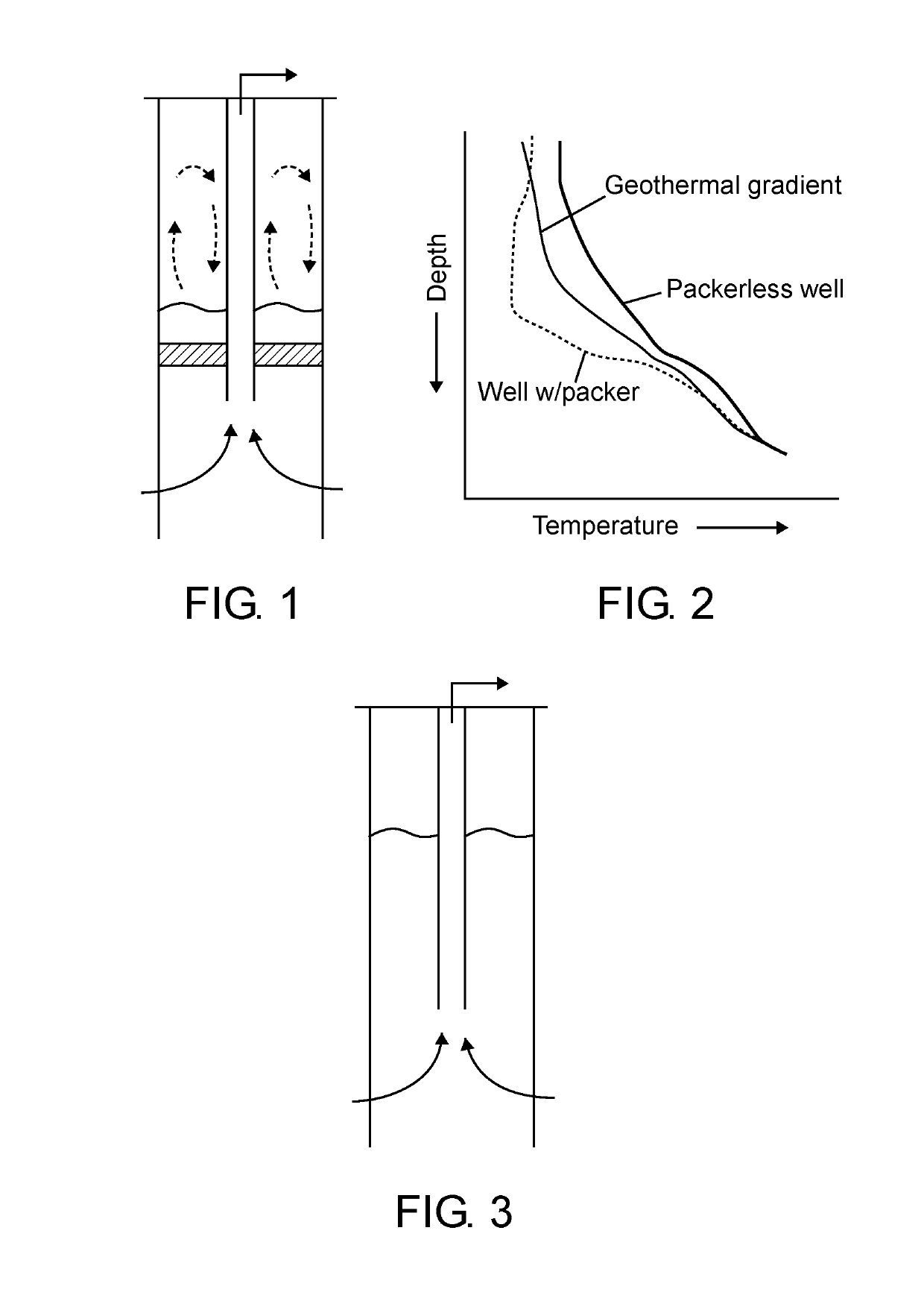
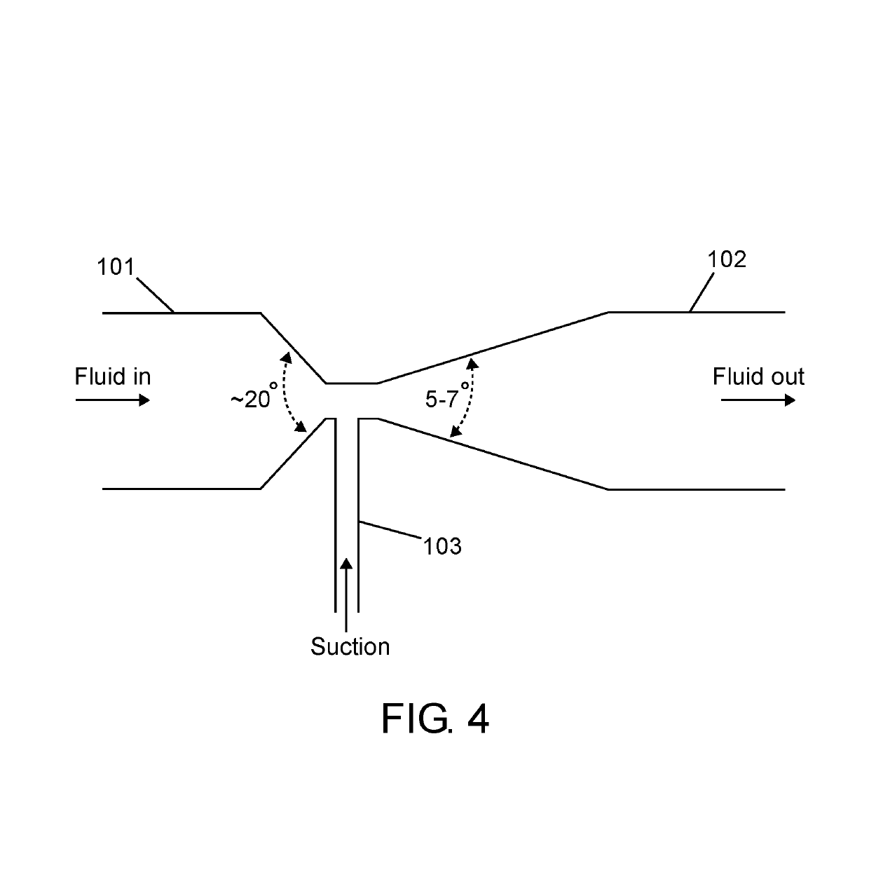
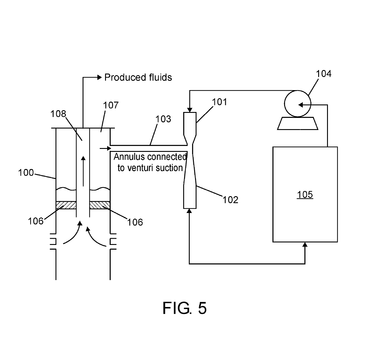
A method for preventing wax deposition in oil wells with packers is disclosed. The method includes feeding a motive fluid from a storage tank to an ejector having a converging section for inlet of the motive fluid, a diverging section for outlet of the motive fluid, and a constricted section with an opening in between the converging section and the diverging section; removing a water and water vapor from an annulus of the oil well using the ejector, wherein flowing of the motive fluid through the converging section and diverging section of the ejector creates a pressure loss and increases the velocity of the motive fluid, which creates suction in the constricted section to evacuate water and vapor from the annulus of the oil well, thereby remediating wax deposition in the oil well.

Description

CROSS-REFERENCE TO RELATED APPLICATIONS[0001]This application is the United States national phase of International Application No. PCT / IB2015 / 050843 filed Feb. 4, 2015, and claims priority to Indian Patent Application No. 146 / KOL / 2014 filed Feb. 5, 2014, the disclosures of which are hereby incorporated in their entirety by reference.TECHNICAL FIELD OF THE INVENTION[0002]The present invention relates generally to the remediation of heavy restriction caused by wax deposition in oil wells having packers that have abnormally low wellbore temperatures on account of wellbore reflux. More particularly, the invention provides a method for preventing wellbore cooling, thus minimizing wax deposition in oil wells having packers.BACKGROUND AND THE PRIOR ART[0003]Crude petroleum liquid, commonly known as ‘crude oil’, contains varying amounts (1-25% w / v) of paraffin waxes as well as microcrystalline waxes. The waxes are soluble in crude oil at the reservoir temperature and pressure, but crystalli...

Claims


Application Information

Patent Timeline
Patent Type & Authority Patents(United States)
IPC IPC(8): E21B37/06E21B37/00E21B43/12E21B33/12
CPCE21B37/00E21B43/124E21B33/12E21B43/123
Inventor DHODAPKAR, PRASHANT
Owner OIL INDIA
Learn More