Wheel driving system for construction machinery

a technology of construction machinery and driving system, which is applied in the direction of electric propulsion mounting, vehicle sub-unit features, transportation and packaging, etc., can solve the problems of low fuel efficiency and work efficiency of construction machinery including high-capacity electric motors, large and heavy electric motors capable of producing high torque, and deterioration of fuel efficiency and work efficiency of construction machinery. , to achieve the effect of low maximum output torque, low driving torque and high conversion torqu

Active Publication Date: 2019-05-07
View PDF12 Cites 0 Cited by
  • Summary
  • Abstract
  • Description
  • Claims
  • Application Information

AI Technical Summary

Benefits of technology

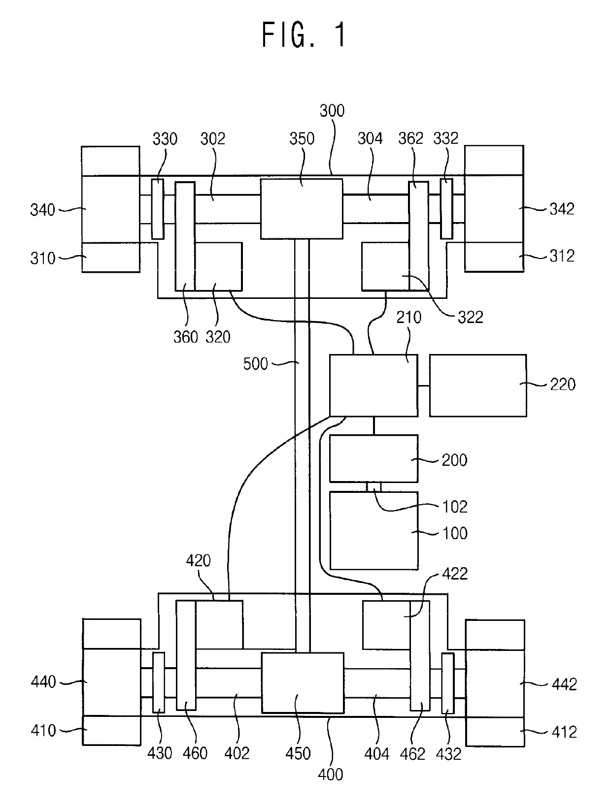
[0008]Example embodiments provide a wheel driving system capable of improving wheel driving efficiency.
[0018]When hybrid construction machinery performs a high load work, a load may be concentrated on a front axle or a rear axle of the construction machinery. Especially, in a forward excavation work state of a wheel loader, a traction work state of a tractor, etc, a load may be concentrated on the front axle, no load or a little load may be exerted on the rear axle. In this case, it may be preferable that the front axle and the rear axle include high capacity electric motors capable of producing high torque respectively. Accordingly, because the high capacity electric motors are relatively big and heavy, fuel efficiency and work efficiency of the construction machinery including the high capacity electric motors may be relatively low.
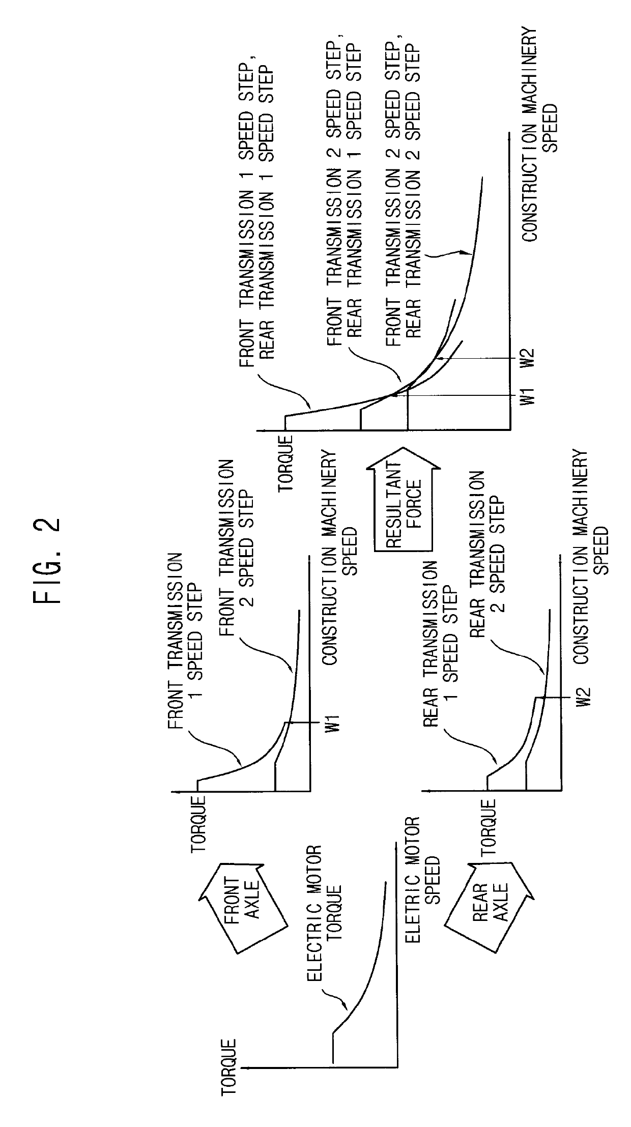
[0019]In a wheel driving system in accordance with example embodiments, light-weight and compact front and rear electric motors having a relatively low maximum output torque may be connected to front and rear transmissions respectively, and a low driving torque respectively generated by the front and rear electric motors may be converted into a high conversion torque such that a front wheel and a rear wheel are driven by the conversion torque. Accordingly, the weight and price of the construction machinery may be decreased, and fuel efficiency and work efficiency of the construction machinery may be improved. Additionally, because the front transmission and the rear transmission have different shift ratios, the wheel driving system may satisfy a traction load required for the construction machinery and perform the high load work without torque transfer interruption during shifts.
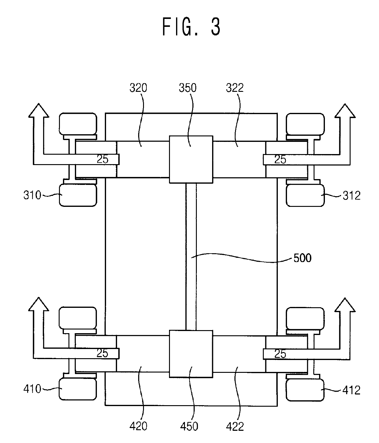
[0020]Even when the rear wheel driven by the rear axle does not exert the conversion torque on the ground, the conversion torque produced by the rear axle may be transmitted to the front axle through a central connection unit. Accordingly, the total load may be shared by the front electric motor and the rear electric motor, the loads exerted on each of the front electric motor and the rear electric motor may be reduced, and light-weight and compact electric motors having a relatively low maximum output torque may be used in the construction machinery. Thus, fuel efficiency and work efficiency of the construction machinery may be improved due to light weight.

Problems solved by technology

Generally, the electric motor capable of producing high torque may be relatively big and heavy.
Because the size and the volume of the construction machinery including these electric motors are increased, fuel efficiency and work efficiency of the construction machinery may be deteriorated.
Accordingly, because the high capacity electric motors are relatively big and heavy, fuel efficiency and work efficiency of the construction machinery including the high capacity electric motors may be relatively low.

Method used


Image

  • Wheel driving system for construction machinery
  • Wheel driving system for construction machinery
  • Wheel driving system for construction machinery

Examples


Embodiment Construction

[0026]Various example embodiments will be described more fully hereinafter with reference to the accompanying drawings, in which some example embodiments are shown. The present inventive concept may, however, be embodied in many different forms and should not be construed as limited to the example embodiments set forth herein. Rather, these example embodiments are provided so that this description will be thorough and complete, and will fully convey the scope of the present inventive concept to those skilled in the art. In the drawings, the sizes and relative sizes of layers and regions may be exaggerated for clarity.

[0027]It will be understood that when an element or layer is referred to as being “on,”“connected to” or “coupled to” another element or layer, it can be directly on, connected or coupled to the other element or layer or intervening elements or layers may be present. In contrast, when an element is referred to as being “directly on,”“directly connected to” or “directly ...


PUM


Abstract

A wheel driving system includes a generator connected to an engine and configured to generate electrical energy, a front axle configured to drive a front wheel and including a front electric motor configured to produce a driving torque and a front transmission configured to convert the driving torque into a conversion torque and transmit the conversion torque to the front wheel via a front drive shaft, a rear axle configured to drive a rear wheel and including a rear electric motor configured to produce a driving torque and a rear transmission configured to convert the driving torque into a conversion torque and transmit the conversion torque to the rear wheel via a rear drive shaft, and a central connection unit operatively connected to the front drive shaft and the rear drive shaft and configured to transmit the conversion torque between the front axle and the rear axle.

Description

CROSS REFERENCE TO RELATED APPLICATION[0001]This application is the National Phase application of International Application No. PCT / KR2015 / 005226, filed May 26, 2015, which is based upon and claims the benefits of priorities under 35 U.S.C § 119(a) of Korean Patent Application No. 10-2014-0063772, filed on May 27, 2014 with the Korean Intellectual Property Office (KIPO), the entire contents of which are incorporated herein by reference.BACKGROUND[0002]1. Field[0003]Example embodiments relate to a wheel driving system for construction machinery. More particularly, Example embodiments relate to a wheel driving system for hybrid construction machinery.[0004]2. Description of the Related Art[0005]Recently, researches on hybrid driving system using an engine and a generator as a power source have been increased. Because construction machinery including the hybrid driving system has to perform a high load work as well as a general drive, an electric motor respectively included in a front ...

Claims


Application Information

Patent Timeline
Patent Type & Authority Patents(United States)
IPC IPC(8): B60K6/547B60K6/22B60K6/52B60K6/26F16H61/02B60W10/14F16H61/04B60K17/06B60K17/35B60K7/00B60K17/16B60K17/356B60K23/08B60K1/04B60K17/04
CPCB60K6/52B60K6/26B60K6/547B60K7/0007B60K17/06B60K17/165B60K17/35B60K17/356B60K23/0808B60W10/14F16H61/0213F16H61/04B60K6/22Y10S903/919B60K1/04B60K17/043B60K2007/0061B60Y2200/41B60Y2200/91B60Y2200/92B60Y2400/204B60Y2400/61B60Y2400/80B60Y2400/82Y10S903/916B60K6/46Y02T10/62
Inventor JUNG, EUN-SOOKIM, CHANG-HYUNKIM, DONG-MOKCHO, LEE-HYOUNG
Why Eureka
Try Eureka