Omnidirectional building integrated wind energy power enhancer system

a technology of integrated wind energy and enhancer system, which is applied in the direction of machines/engines, renewable energy generation, greenhouse gas reduction, etc., can solve the problems of unsightly nature, increased maintenance costs, and inability to adapt to the design of existing wind turbines as is economically feasible, so as to achieve the highest possible pressure differential, direct airflow the effect of most effective and efficient, and increased wind flow

Active Publication Date: 2019-05-07
AEROMINE TECH
View PDF12 Cites 9 Cited by
  • Summary
  • Abstract
  • Description
  • Claims
  • Application Information

AI Technical Summary

Benefits of technology

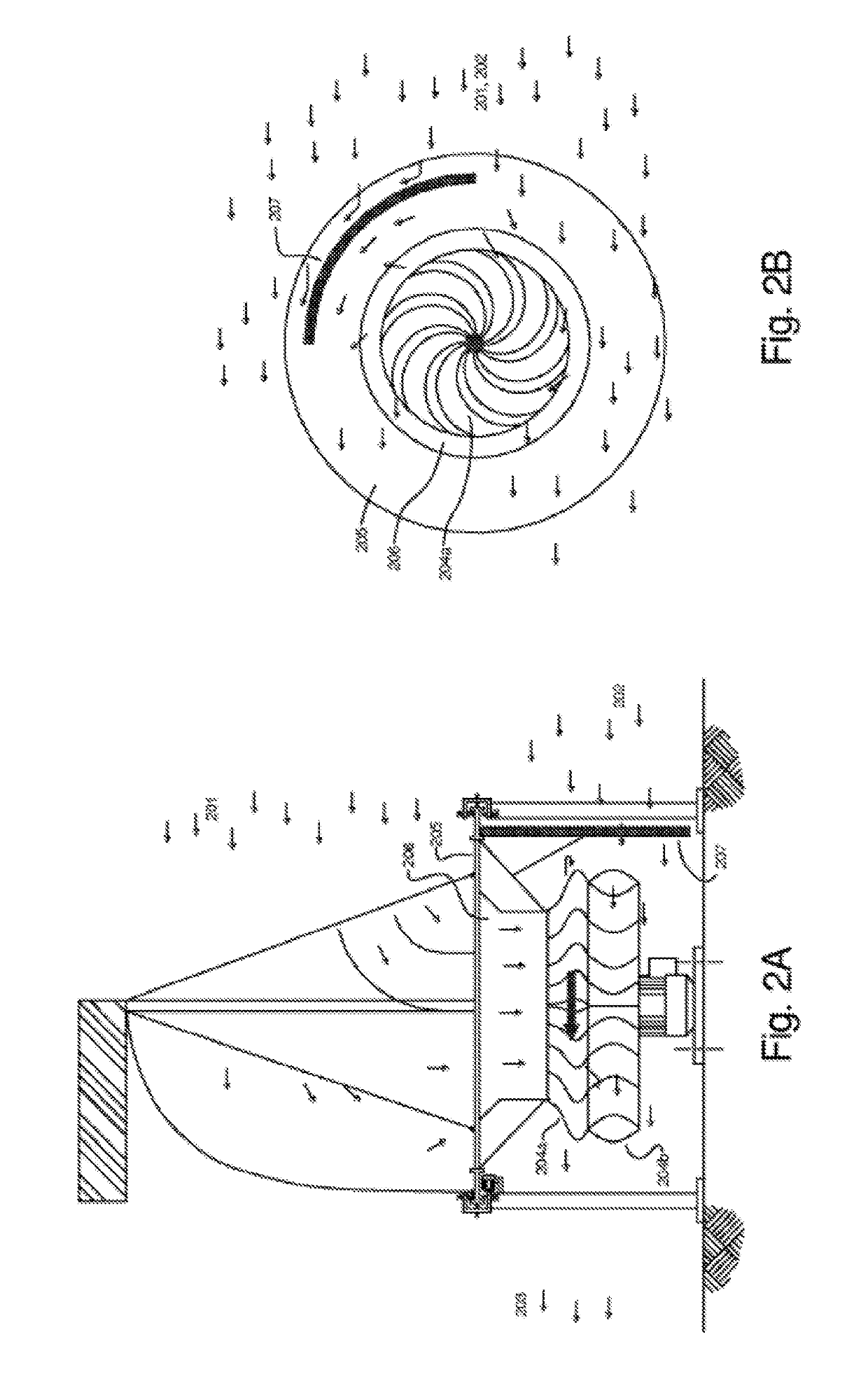
[0016]In one embodiment, the present invention uses an adjustable air scoop inlet section, an air turbine section, and an adjustable outlet section—each having variable geometry and of a unique design—to utilize a first phase of the prevailing wind to provide power. The air turbine and outlet sections can also utilize a second phase of the prevailing wind as a second stage of power production. This second phase wind, flowing directly through and / or around the air turbine and outlet sections, can also utilize an additional full or partial exit drag curtain and / or exit barrier to enhance second stage power production from the overall air turbine system. The air turbine rotor and outlet section can additionally be configured such that the turbine exhaust air enters the outlet section in a manner that re-entrains the exhaust air into the downstream prevailing wind at reduced velocities and at negative pressure conditions. These negative pressure conditions can be further enhanced by use of an adjustable exit drag curtain and / or exit barrier.
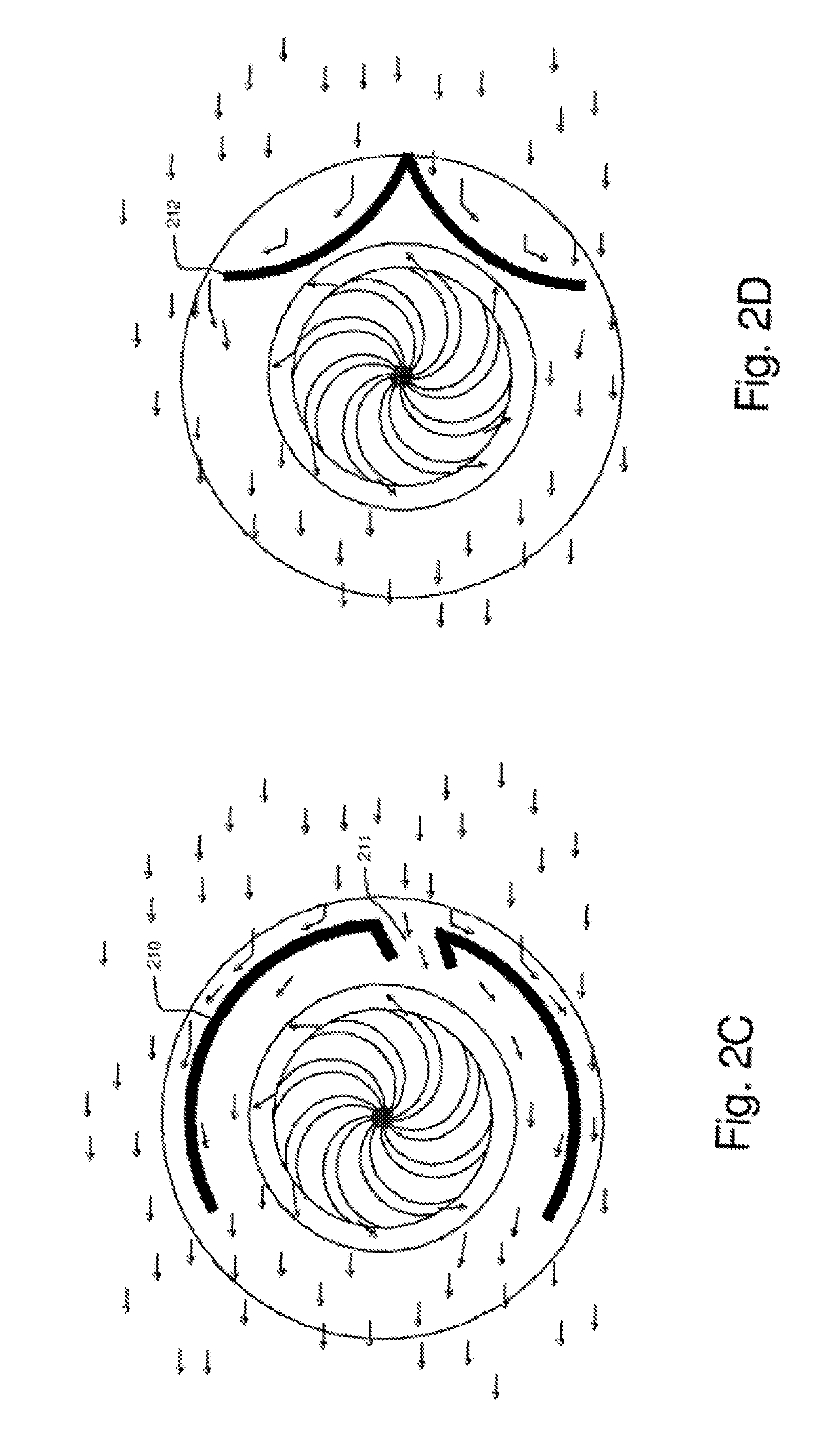
[0018]For the purposes of this patent application, the terms “outlet section”, “outlet chamber”, “outflow chamber” and “exit space” are considered synonymous. The “impingement chamber” serves as a special feature of the outlet section when used with multi-phased wind applications. The terms “inlet section”, “inlet chamber” and “inflow chamber” are also considered synonymous. Drag curtains, located downstream of the air turbine in the direction of exhaust air flow, are configured to create both reduced exhaust air velocities and an enhanced vacuum effect within the outlet section. Exit barriers, located in the upstream air flow to the air turbine rotor assembly, are configured to more efficiently inject at least a part of the second phase air flow into the air turbine rotor for enhanced power production.
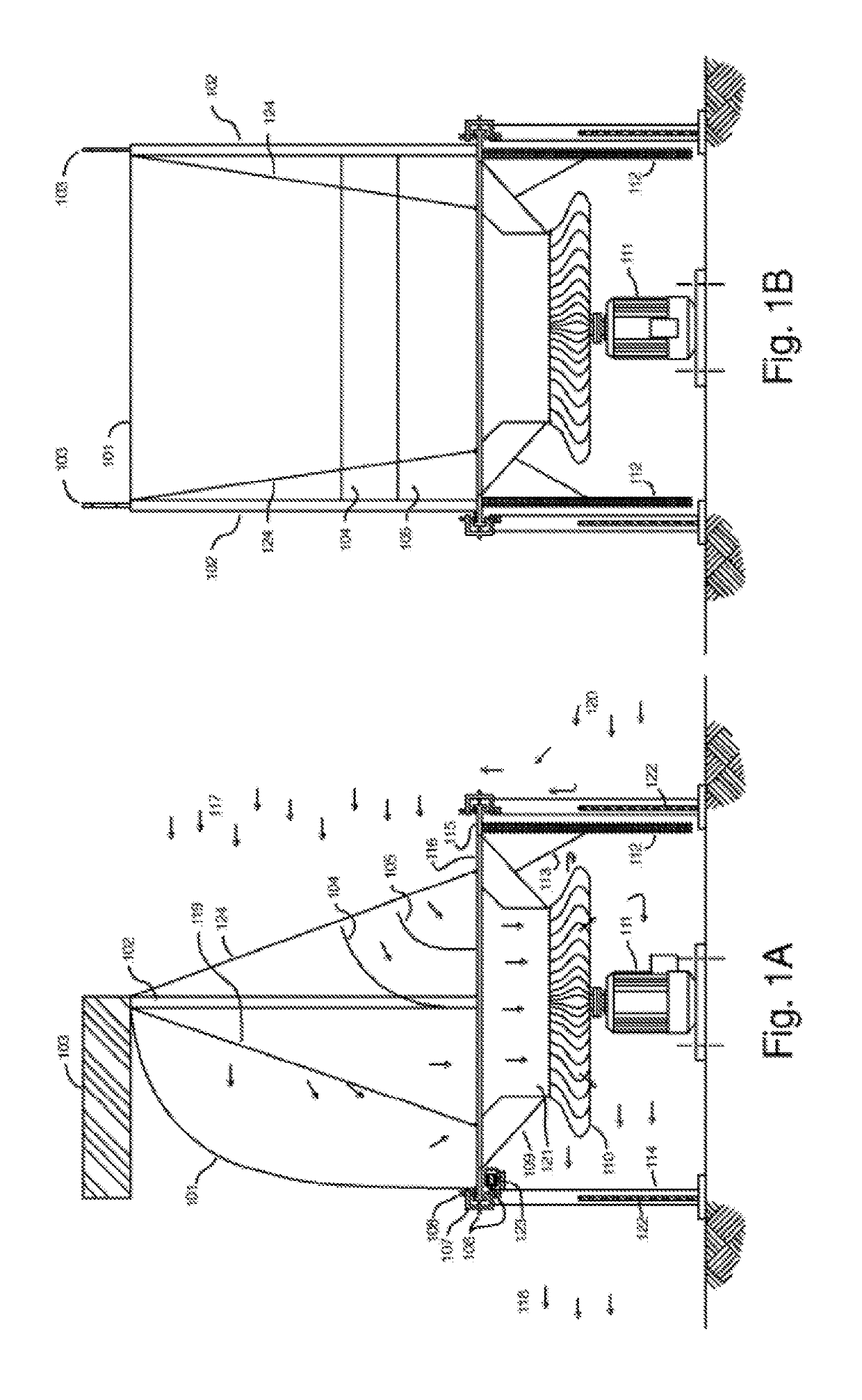
[0028]In an exemplary embodiment, the function of the building integrated wind power inflow chamber is to utilize the upstream surfaces of the building to the maximum extent possible, in order to increase the static pressure to the entrance of the inflow chamber for increased pressure differential creation across the wind turbine rotor assembly and the resulting increased power output. For this purpose, a passively or actively actuated inlet air scoop may be mounted in most cases within the building or within the ducting itself and may be designed to have an oversized inlet cross sectional flow area to reduce the pressure losses associated with the incoming wind. A passively or actively actuated inlet air scoop, configured within the an inlet flow tube or ducting within the building, may direct the incoming air flow from a horizontal to a vertical direction and into a flow tube that leads to a vertical axis type wind turbine.
[0029]With building integrated wind energy power enhancer systems the total pressure to the inflow chamber may be higher than the total pressure available from the approaching wind as there may be an increased static pressure resulting from the large upstream impact surface area and configuration of the building relative to the inlet chamber cross sectional flow area. An entire side of a building may funnel airflow into an inflow chamber and the ratio between the upstream building surface area and the inflow chamber cross sectional flow area can be very large. This large ratio increases the pressure in the flow tube and enables higher power generation.
[0035]Either as a supplement or in addition to the above means to force the incoming wind and air streams into the flow tube and wind turbine assembly or assemblies, a series or compliment of automatically controlled guillotine type dampers may be employed for more stable wind flows coming from more or less fixed directions relative to the building and wind turbine system. Alternatively, for more gusty and variable wind flows and / or variable direction of wind flows to and around the building, a compliment of either passively or actively actuated flexible inlet, and in some cases even outlet flexible curtains or sheets may be employed around the building at the various inlets and outlets to the inlet and outlet flow chambers, as appropriate, to enhance and / or sustain the pressure differentials developed by the upstream and downstream wind flows. The flexible curtains or sheets may be configured to maintain a more stable differential pressure with resultant increased wind inflow and / or outflow across the wind turbine rotor assembly and thereby enhance the effective performance with an improved capacity factor for the overall wind turbine system under more gusty wind conditions of operation. These flexible air curtains or sheets shall be designed in both size and aerodynamic weight or buoyancy so as to operate with essentially no pressure loss of the wind through the flexible curtains or sheets and yet shall also be engineered in size and location within the inflow and outflow chambers to cause a minimum of random or harmonic noise generation while operating in their most effective and efficient manner possible and as required so as to prevent the creation of power robbing wind and air backflows from occurring at all points throughout and within the overall wind turbine system enclosure.

Problems solved by technology

Unfortunately, existing wind turbine designs have not been as widely adapted as is economically feasible.
There are unforeseen problems with public reaction to the unsightly nature of the turbines and their visual dominance on a landscape, especially where there may be multiple installations of air turbines, often moving at different speeds and rotations with respect to each other, which may be viewed at the same time by a casual observer.
There have been other issues.
Existing wind turbines are often high off the ground, which increases maintenance costs due to poor accessibility.
Some turbines have to reduce their operating speeds due to birds colliding with the turbine blades.
There are infrastructure problems, where high voltage transmission lines are unavailable in favorable wind areas.
However, the practicality of the design is highly questionable.
The practical aspects of the design are highly limited.
The venturi design does not consider appropriate methods to re-entrain the turbine exhaust air back into the prevailing wind in an efficient manner, and the design is overly complicated.
Also, the efficiency of the wind ‘catch’ and wind ‘discharge’ has not been carefully planned.
Further, the building is a fixed size, and it is difficult to optimize the whole design when the wind ‘catch’ area is a constant size.
It is less appealing to have the air intake close to the ground as the wind speed is lower.
However, the design of the air stream through the central opening of the framework and the closed baffles is inadequate.
As stated previously, a relatively large volume of air is needed to create the vacuum needed to draw a significant amount of air vertically, and the effect is not as efficient as other methods.
This design is not configured to catch a prevailing wind from any direction, and the simple structure is likely to be damaged in a high wind.
The overly large design is meant to catch the movement of air from a thermal effect when the air is heated by the sun.
Again, in both of these patents no thought is given to providing a large exit space just after the turbine blades where the prevailing wind is allowed to enter and additionally generate power by rotating the turbine blades.
None of these patents provide a large exit space just after the turbine blades where the prevailing wind is allowed to enter and additionally generate power by rotating the turbine blades.

Method used


Image

  • Omnidirectional building integrated wind energy power enhancer system
  • Omnidirectional building integrated wind energy power enhancer system
  • Omnidirectional building integrated wind energy power enhancer system

Examples


Embodiment Construction

[0118]The present invention is a system designed to produce electricity at cost effective rates in an environmentally friendly manner at power outputs of approximately 0.10 to 1 MWe. It is especially useful in areas where the wind velocity and turbulence increases in places that occur around small hills and tall buildings. It may be employed successfully in the heavily populated downtown sections of major cities. Multiple units can be utilized and may be sized for any given location as the opportunity may arise. Generally speaking, areas with average wind speeds of at least 12 mph are considered to be the most favorable locations for wind power.

[0119]FIGS. 1A-1B show two cross-sectional views of a preferred embodiment, general arrangement of the invention. A large air scoop 101 made from a flexible material, such as used in the sailing industry, is hoisted above a vertical axis power generating turbine 110, 111 in order to utilize the upper prevailing wind 117 and direct the maximum...


PUM


Abstract

An omnidirectional building integrated wind energy power enhancer system is configured to produce electrical power from a wind turbine(s) concealed within and / or on top of a building by means of a flow of pressurized air from the prevailing wind that enters and flows through a portion of a building. A building may provide large exterior surface areas for receiving and directing airflow to the turbine(s). At least a portion of the wind energy power enhancer system is configured within a building, such as between floors, on a single floor, and / or a roof structure. The wind turbine(s) may be configured to receive airflow directly from an inflow chamber that is configured with a building, or from a flow tube coupled with the inflow chamber. Air deflectors may be fixed or dynamic to direct air flow into a flow tube regardless of the direction of the incoming airflow relative to the building.

Description

CROSS REFERENCE TO RELATED APPLICATIONS[0001]This application is a continuation in part of U.S. patent application Ser. No. 14 / 960,286 entitled Building Integrated Wind Power Enhancer System, filed on Dec. 4, 2015 and currently pending, which is a continuation in part of U.S. patent application Ser. No. 13 / 607,614, entitled Dual Wind Energy Power Enhancer System, filed on Sep. 7, 2012 and issued as U.S. Pat. No. 9,273,665, which is a continuation in part of U.S. patent application Ser. No. 13 / 352,259 filed on Jan. 17, 2012 and issued as U.S. Pat. No. 8,403,623, which is a continuation in part of U.S. application Ser. No. 12 / 834,722 filed on Jul. 12, 2010 and currently abandoned, which is a continuation in part of U.S. patent application Ser. No. 12 / 355,411 filed on Jan. 16, 2009 and issued as U.S. Pat. No. 7,753,644, which is a continuation in part of U.S. patent application Ser. No. 11 / 608,658 filed on Dec. 8, 2006 and issued as U.S. Pat. No. 7,488,105 which claims the benefit of U...

Claims


Application Information

Patent Timeline
Patent Type & Authority Patents(United States)
IPC IPC(8): F03D9/45F03D13/20F03D9/25H02K7/18F03D9/00F03D3/04F03D1/04
CPCF03D9/45F03D1/04F03D3/0427F03D9/002F03D9/25F03D13/20H02K7/183F05B2240/9112F03D9/37Y02B10/30Y02E10/72Y02E10/728Y02E10/74
Inventor KRIPPENE, BRETT C
Owner AEROMINE TECH
Why Eureka
Try Eureka