
Processing module and associated method

a processing module and module technology, applied in the field of processing modules for communication devices, can solve the problems of inability to predict actual distance gain, inability to take correct (early) toa measurements, etc., and achieve the effect of improving the auto-correlation of the validation sequen

Active Publication Date: 2019-05-21
NXP BV
View PDF15 Cites 4 Cited by
  • Summary
  • Abstract
  • Description
  • Claims
  • Application Information

AI Technical Summary

Benefits of technology

The patent describes a method for improving the estimation of channel occupancy in a wireless network. By modifying the cross-correlation between parts of the validation sequence and the validation pattern, interference from neighboring channels can be reduced. The method also uses unvalidated channel estimate information to benefit from its improved security and better auto-correlation properties. Additionally, the validation pattern is modified to improve weak signal path detection. The method reduces computational effort by segmenting the validation pattern and inverting bits of each segment. The technical effects of the patent include improved channel occupancy estimation with reduced interference and improved security, as well as improved weak signal path detection with reduced computational effort.

Problems solved by technology

However, conventional approaches to identifying the LoS path for a multi-channel environment are susceptible to ‘attacks’ that can result in a false ‘first’ path being detected, and thus an incorrect (early) ToA measurements being taken.
Since there is no synchronization to the legitimate signal, the actual distance gain is hard to predict.

Method used


Image

  • Processing module and associated method
  • Processing module and associated method
  • Processing module and associated method

Examples


example b

[0166 uses prior knowledge of the insecure channel estimate, C, of the impulse response and the secure training sequence, PSTX. The procedure is similar to example A but no multi-path components are zeroed from the insecure channel estimate, C. An expected correlator output is pre-calculated and subtracted from the actual correlator output. If the result is random noise (i.e. no value exceeds the detection threshold), then all paths detected in the insecure channel estimate, C, are genuine and the ranging measurement can be accepted as valid. That is, in example B, validation is achieved by removing from the secure channel estimate all expected path components from the insecure channel estimate. One implementation of example B is described below with reference to steps (a) to (d):[0167]a. The cross-correlation, CCSRX, of transmitted secure training sequence, PSTX, and the correlation pattern of the receiver, PSRX is calculated:

CCSRX(n)=PSTX(n)⊗PSRX(−n)[0168]b. The cross-correlation ...

example c

[0173 uses prior knowledge of the insecure channel impulse response, C, and the secure training sequence PSRX. The main lobe of cross-correlation result of the correlation pattern, PSRX, (validation pattern) and the secure training sequence, PSTX, (validation sequence) is set to zero, so that only the side-lobes remain. This result is then convolved with the known, insecure channel impulse response to calculate the expected cross-correlation contribution of the channel caused only by the side-lobes. The expected side-lobe contribution is then subtracted from the actual received correlator output determined for the secure training sequence. One implementation of example C is described below with reference to steps (a) to (d):[0174]a. The cross-correlation of transmitted secure training sequence, PSTX, and the correlation pattern of the receiver, PSRX is calculated to provide a first cross-correlation function, CCSRX:

CCSRX(n)=PSTX(n)⊗PSRX(−n)

FIG. 27 illustrates a relative amplitude ag...

example f

[0196 is based on example D but uses the secure channel estimate, CS, (without side-lobe correction) as a reference to calculate the contribution of the side-lobes, rather than the insecure channel estimate, C, as in example D. This approach is similar to that described previously with reference to example E. Example F is therefore also suitable for use where no insecure channel estimate is available. The use of the secure channel estimate instead of the insecure channel estimate introduces residual errors because side-lobes are inadvertently considered as valid multipath components. The residual error can be reduced by applying an iterative algorithm. As with examples A to E, example F may also be performed by the validator 1170 of the receiver of FIG. 11. One implementation of example F is described below with reference to steps (a) to (d):[0197]a. The cross-correlation of transmitted secure training sequence, PSTX, and the correlation pattern of the receiver, PSRX is calculated t...


PUM


Abstract

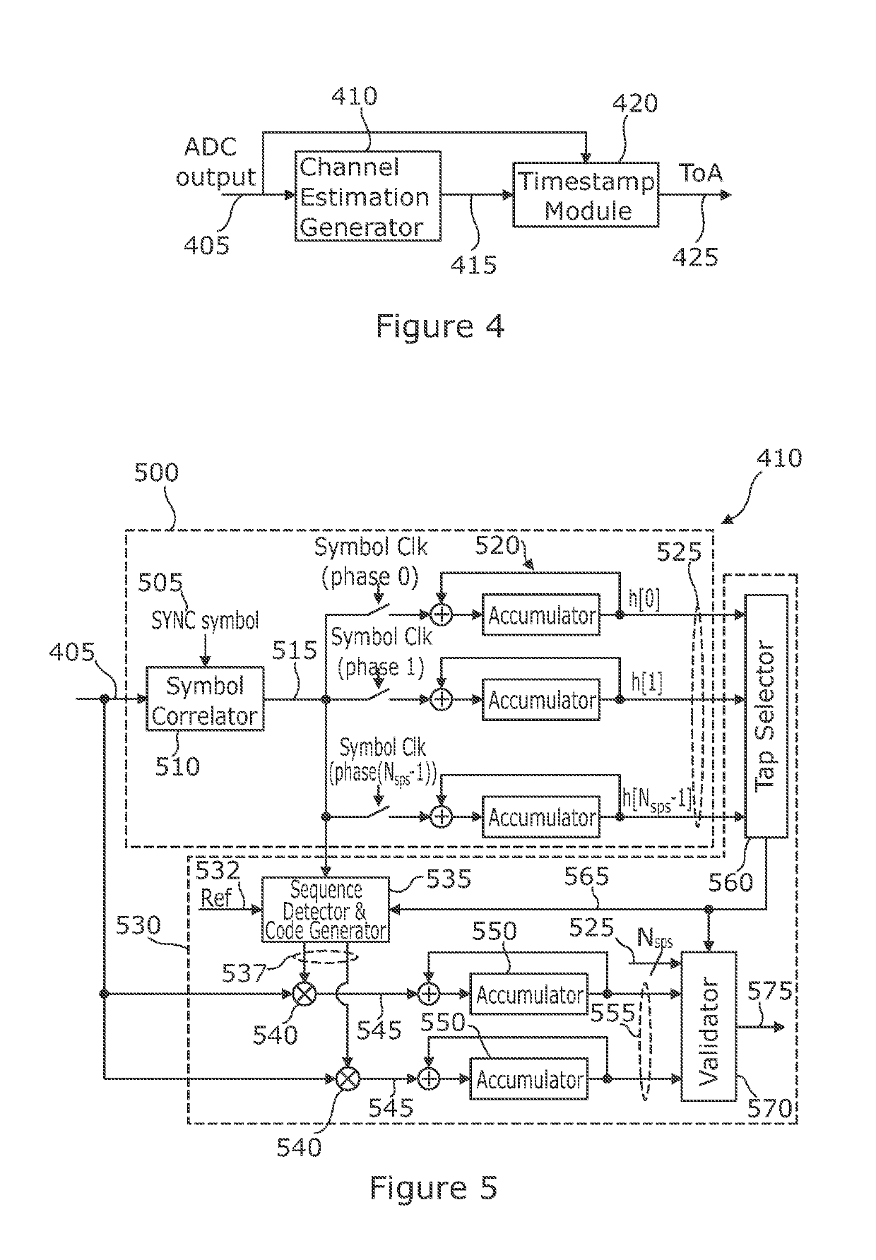
A processing module for a receiver device. The processor module comprises a channel estimate generation component arranged to output channel estimate information for a received signal, and a timestamping module arranged to determine a ToA measurement for a marker within a packet of the received signal based at least partly on the channel estimate information for the received signal generated by the channel estimate generation component. The channel estimate generation component comprises a validation component arranged to derive a validation pattern for the packet within the received signal for which a ToA measurement is to be determined, identify a section of the packet containing a validation sequence, and perform cross-correlation between at least a part of the validation sequence within the packet and at least a part of the validation pattern to generate channel estimate validation information.

Description

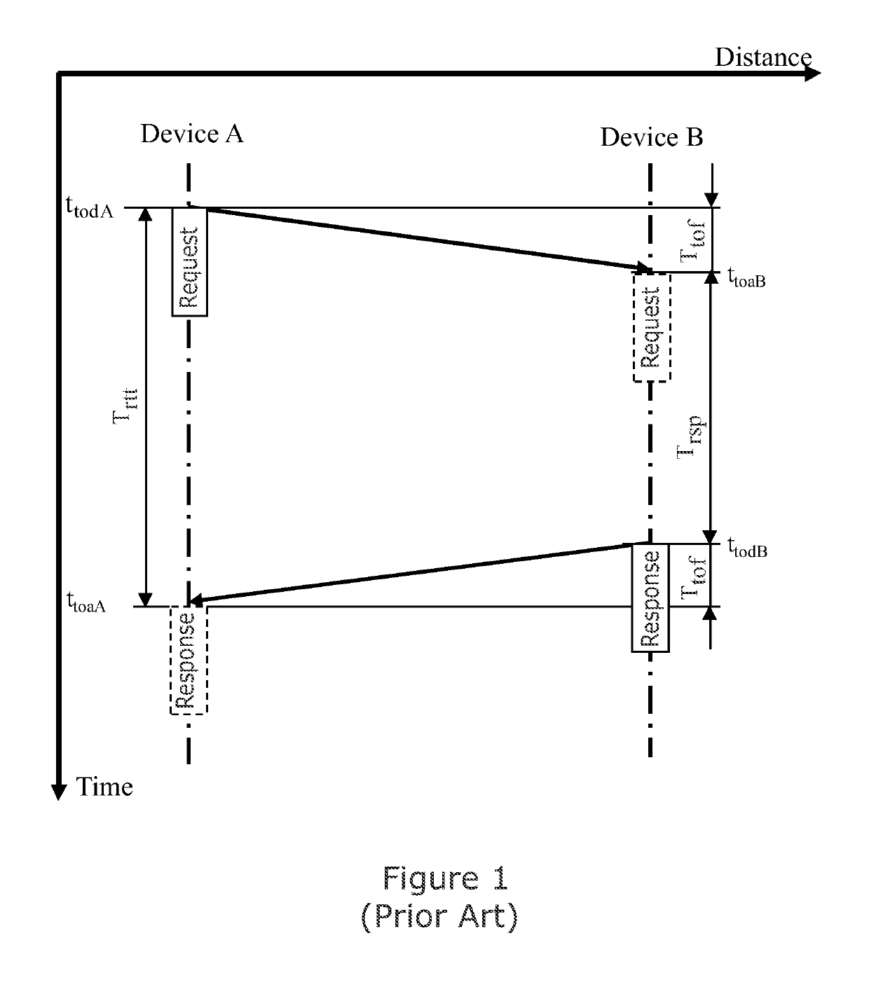
CROSS-REFERENCE TO RELATED APPLICATIONS[0001]This application claims the priority under 35 U.S.C. § 119 of European Patent application no. 16198525.4, filed on Nov. 11, 2016, the contents of which are incorporated by reference herein.FIELD OF THE INVENTION[0002]This invention relates to a processing module for a communication device and a method therefor of estimation of a propagation channel model.BACKGROUND OF THE INVENTION[0003]Wideband Radio Frequency (RF) applications have been developed that are capable of accurate distance measurement between two or more wireless devices. These measurements are based on Time-of-Flight (ToF) calculations which are derived by accurate determination of departure and arrival times of RF packets between two devices. RF packets travel at the speed of light and thus a calculated ToF allows determination of the distance between devices. Such a procedure is commonly called ‘Ranging’. One practical application of Ranging is ‘Distance Bounding’ whereby ...

Claims


Application Information

Patent Timeline
Patent Type & Authority Patents(United States)
IPC IPC(8): H04B1/00G01S7/285H04L25/02H04B17/30G01S13/76G07C9/00
CPCH04B17/30G01S7/285G01S13/767H04L25/0202G01S13/765G07C9/00309H04L25/03
Inventor KUCHLER, WOLFGANGBAIER, THOMASLAFER, MANUEL
Owner NXP BV
Learn More