Sealing arrangement for a sliding caliper

a sealing arrangement and disc brake technology, applied in the direction of engine seals, axially engaging brakes, brake types, etc., can solve the problem of too small to allow the sealing bead to pass through, and achieve the effect of convenient location

Active Publication Date: 2019-05-28
MEI BRAKES LTD
View PDF16 Cites 1 Cited by
  • Summary
  • Abstract
  • Description
  • Claims
  • Application Information

AI Technical Summary

Benefits of technology

[0015]Because the sealing bead is held at least partly within the axial bore, it is less prone to work loose than in prior art designs where the bead is compressed between the retaining ring and the end of the guide pin. Also, the length required for sealing is minimised. The retaining ring may overlie the end of the guide pin with a clearance sufficient to allow part of the elastomeric mid portion of the sealing boot to pass between the ring and the guide pin, but too small to allow the sealing bead to pass through. Preferably, there is enough clearance between the retaining ring and the end of the guide pin to avoid compressing the mid portion of the sealing boot.
[0020]The retaining clip may include a groove adjacent to the retaining ring for receiving the sealing bead. In other words, the retaining clip may extend into the bore of the guide pin from the retaining ring and may include a secondary ring, the sealing bead being located in a groove between the retaining ring and the secondary ring. This allows the sealing bead to be easily located during assembly.
[0021]The sealing bead may have an angled profile, for example it may form a trapezoidal ring. An angled profile and in particular a trapezoidal ring allows the bead to be more effectively held between the retaining ring and the guide pin.
[0023]The widened mouth will effectively reduce the thickness of the guide pin wall towards the end of the guide pin. This reduced thickness creates a cavity in which the sealing bead may sit, surrounded by the retaining ring, secondary ring, other parts of the retaining clip, and the wall of the guide pin.
[0032]The whole assembly, including the grooved ring, sealing boot and integral retainer sits in the small space between the caliper and the carrier. Because the integral retainer passes along the guide pin, underneath the seat for the sealing bead at the other end of the boot, the arrangement is highly compact, and allows even very closely spaced sliding caliper arrangements to be properly sealed at the end of the guide pin, facing the carrier.

Problems solved by technology

The retaining ring may overlie the end of the guide pin with a clearance sufficient to allow part of the elastomeric mid portion of the sealing boot to pass between the ring and the guide pin, but too small to allow the sealing bead to pass through.

Method used


Image

  • Sealing arrangement for a sliding caliper

Examples


Embodiment Construction

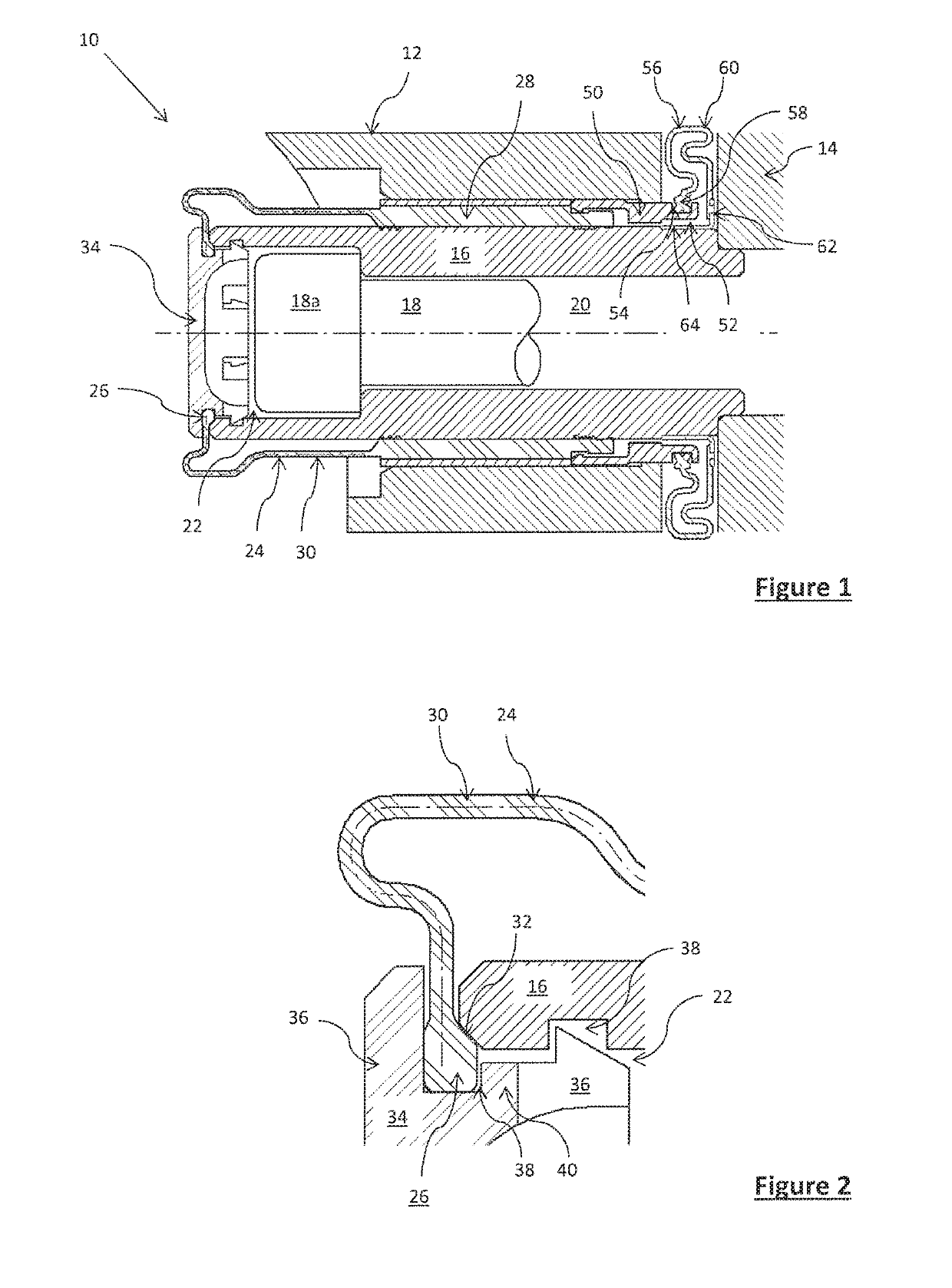
[0037]Referring firstly to FIG. 1, part of a sliding caliper air disc brake is indicated generally at 10. The brake includes a caliper 12 and a carrier 14. A guide pin 16 is bolted to the carrier by means of guide pin bolt 18. Note that although the bolt 18 is shown cut-away in the Figure, in fact it passes all the way through bolt hole 20 in the guide pin 16 to fix the guide pin 16 to the carrier 14. A counterbore 22 is provided in the end of the guide pin 16 facing away from the carrier 14. The counterbore 14 receives the head 18a of the bolt 18.

[0038]The guide pin is substantially cylindrical and extends away from the carrier 14, to the left in the Figure. When installed on a vehicle, this is usually the direction towards the centre of the vehicle.

[0039]Only a small portion of the caliper 12 is shown in the drawings. The caliper 12 includes a bore which receives the guide pin 16 which in turn is bolted to the carrier 14. When the brake pads wear, the caliper 12 slides relative to...


PUM


Abstract

Sealing means are disclosed for preventing the ingress of water and dirt between a brake caliper and the carrier guide pin. At the end of the guide pin facing away from the brake carrier, a retaining clip holds a sealing bead of a sealing boot at least partially within an axial bore of the guide pin. At the end of the guide pin which faces towards the carrier, a sealing boot is provided seated on a ring which in turn is attached to the caliper. The other end of the sealing boot is attached to the guide pin, in a space between the guide pin and the ring. The sealing means at either end are compact, and provide effective sealing where there is not enough space to provide known sealing means.

Description

CROSS REFERENCE TO RELATED APPLICATION[0001]This application claims the benefit of priority from GB Patent Application No. GB 1608698.5 filed on May 18, 2016, the contents of which are incorporated by reference.TECHNICAL FIELD OF THE INVENTION[0002]The present invention relates to a sealing arrangement for a sliding caliper disc brake, particularly an air disc brake for a large road vehicle.BACKGROUND OF THE INVENTION[0003]In a sliding caliper disc brake, the brake pad on one side moves with respect to the caliper, towards the disc, when the brake is actuated and with pad wear. The brake pad on the other side of the disc is fixed relative to the caliper. To provide a clamping force to both sides of the disc, the whole caliper moves axially relative to the brake disc, when the brake is actuated, to bring the brake pad which is fixed to the caliper into contact with the brake disc. The whole caliper also moves axially relative to the brake disc to allow for wear of the pad and disc.[0...

Claims


Application Information

Patent Timeline
Patent Type & Authority Patents(United States)
IPC IPC(8): F16D65/095F16J3/04F16J3/02F16D55/2265F16D65/097F16D65/00F16D55/227
CPCF16D65/0973F16D55/2265F16D55/22655F16D65/0068F16J3/02F16J3/042F16D65/005F16D55/227F16D65/0025F16D65/0087F16J15/52
Inventor ROBERTS, PAULJACKSON, JONATHAN LESLIE CHRISTOPHERDAWSON, ANDREWRANDALL, ALEXIS JONATHAN
Owner MEI BRAKES LTD
Why Eureka
Try Eureka