Coil assembly, structure for attaching coil assembly, and electrical connection box

a technology for coil assemblies and electrical connections, applied in the direction of transformers/react mounting/support/suspension, inductance with magnetic cores, inductance, etc., can solve the problems of abnormal noise generation, fixing method, method needs to be improved,

Active Publication Date: 2019-05-28
AUTONETWORKS TECH LTD +2
View PDF6 Cites 2 Cited by
  • Summary
  • Abstract
  • Description
  • Claims
  • Application Information

AI Technical Summary

Benefits of technology

[0008]This configuration has the following effects. In general, if a component is to be fixed forcibly, the component warps due to a dimensional error of the component and an excessive force is applied to the component. In this configuration, the coil unit is fixed to the resin member via the coil case. Therefore, warping caused by a dimensional error of a component or an error in an assembling position can be absorbed between the coil case and the coil unit. Therefore, compared to a coil unit that is directly fixed to the resin member, it is possible to prevent a strong force from being applied to the coil unit and the magnetic core of the coil unit is unlikely to crack. Moreover, since the fixing portion of the coil case has elasticity, warping can also be absorbed by the fixing portion. Therefore, the magnetic core is less likely to crack.
[0022]According to a technique disclosed in this specification, it is possible to provide a coil assembly, a structure for attaching a coil assembly, and an electrical connection box according to which cracks are unlikely to occur and abnormal noises are unlikely to be generated.

Problems solved by technology

However, the above-described fixing method is problematic in that the core easily cracks due to a strong force being locally applied to only a location at which the plate spring is in contact with the core, and thus the fixing method needs to be improved.
Also, the fixing method is problematic in that abnormal noises are generated by air vibration between the ferrite core and the coil due to magnetostriction.
In general, if a component is to be fixed forcibly, the component warps due to a dimensional error of the component and an excessive force is applied to the component.
Since air vibration caused by magnetostriction is eliminated due to a configuration in which the inside of the coil case is filled with the potting material, abnormal noises are unlikely to be generated.

Method used


Image

  • Coil assembly, structure for attaching coil assembly, and electrical connection box
  • Coil assembly, structure for attaching coil assembly, and electrical connection box
  • Coil assembly, structure for attaching coil assembly, and electrical connection box

Examples


embodiment 1

[0055 will be described with reference to FIGS. 1 to 21.

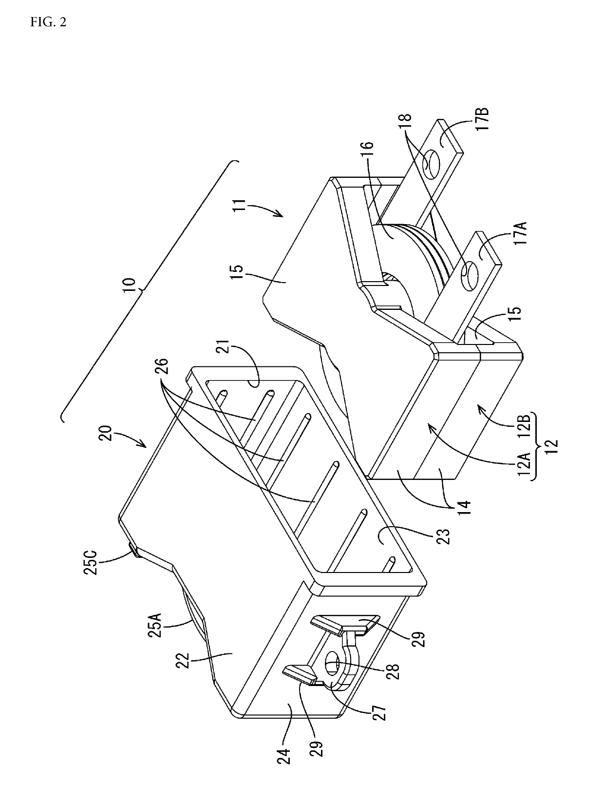
[0056]A coil assembly 10 of the present embodiment includes a choke coil (an example of a coil unit) 11, a coil case 20 that accommodates the choke coil 11, and a potting material 60 filled into the coil case 20 (see FIGS. 1, 2, and 12). Hereinafter, in the following description, the terms “top”, “bottom”, “right”, “left”, “front”, and “rear” respectively refer to the up, down, right back, left front, right front, and left back in FIG. 2.

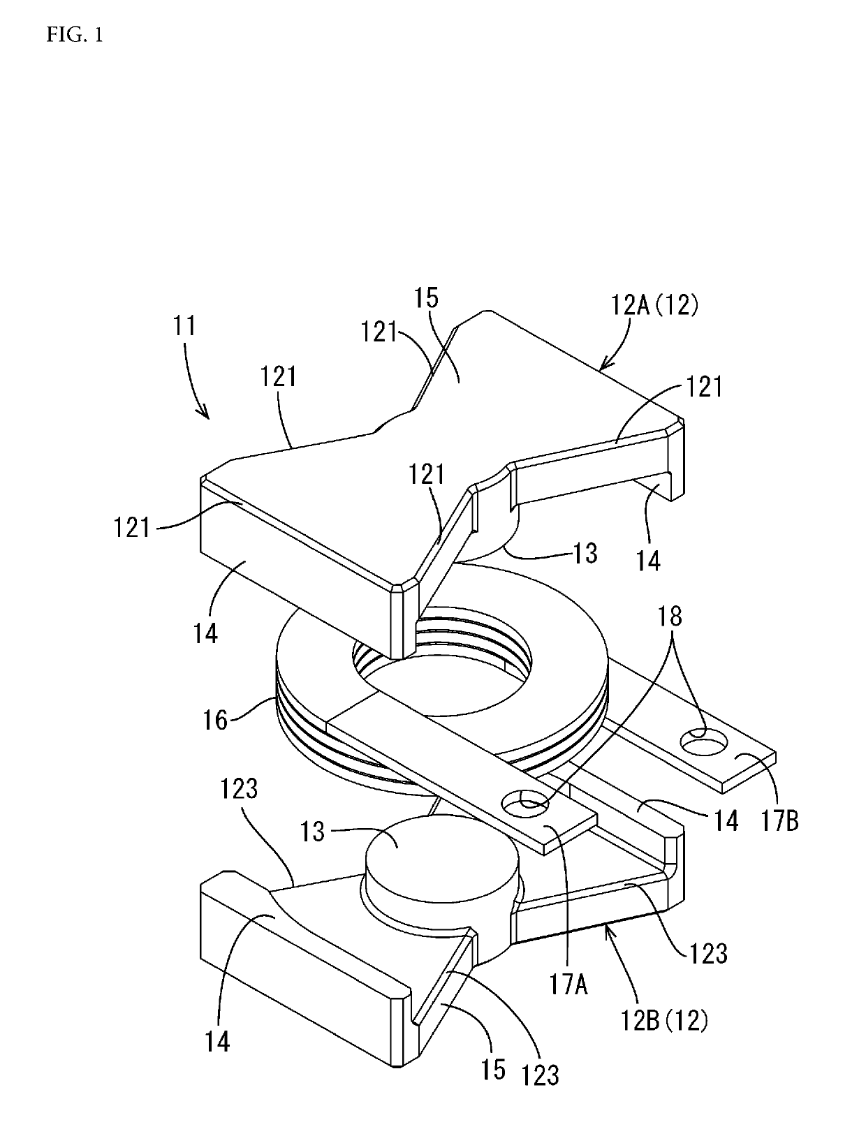
[0057]The choke coil 11 has a magnetic core 12 and an edgewise coil 16. The magnetic core 12 is a so-called PQ core, and as shown in FIG. 1, includes a pair of a first core 12A and a second core 12B that have the same shape and are mounted to each other. The first core 12A and the second core 12B has a cylindrical winding portion 13, a pair of approximately plate-shaped legs 14 that sandwich the winding portion 13 and extend in parallel to each other in the axial direction of the winding portio...

embodiment 2

[0119]As described above, in Embodiment 2, the coil assembly 310 can be positioned with respect to the coil rest 32. Thus, shifting the relative position of the coil assembly 310 to the coil rest 32 can be suppressed. Therefore, since the positions of the fixing holes 35 of the coil rest 32 approximately match the positions of the attaching holes 28 of the fixing portions 27 provided on the coil assembly 310, a screwing operation of fixing the coil assembly 310 to the coil rest 32 can be easily performed.

[0120]Positional shifting between the connection terminals 70A and 70B installed on the outer case 30 and the connection portions 17A and 17B of the choke coil 11 can also be suppressed. Thus, a screw fastening operation of connecting these can also be easily performed.

[0121]Also, the coil assembly 310 can be positioned in two directions, namely, the X-direction and the Y-direction, and shifting the relative position of the coil assembly 310 to the coil rest 32 can be further suppre...


PUM

PropertyMeasurementUnit
angleaaaaaaaaaa
inclination angleaaaaaaaaaa
shapeaaaaaaaaaa

Abstract

A coil assembly includes a coil unit in which a coil obtained by winding a winding wire is disposed around a magnetic core, a coil case that accommodates the coil unit, and a potting material with which an inside of the coil case is filled, and the coil case has an elastic fixing portion that is attachable to a resin member to which the coil case is to be fixed. The above-described configuration makes it possible to provide a coil assembly that is unlikely to crack and generate abnormal noises.

Description

CROSS-REFERENCE TO RELATED APPLICATIONS[0001]This application is the U.S. national stage of PCT / JP2015 / 062834 filed Apr. 28, 2015, which claims priority of Japanese Patent Application JP 2014-138428 filed Jul. 4, 2014.FIELD OF THE INVENTION[0002]A technique disclosed in this specification relates to a coil assembly, a structure for attaching a coil assembly, and an electrical connection box.BACKGROUND OF THE INVENTION[0003]Conventionally, examples of a transformer in which a coil unit is sandwiched between paired cores include a transformer in which a toric coil unit is disposed around a cylindrical protrusion of a pair of ferrite cores called “PQ core”.[0004]Examples of a method for fixing the above-described transformer to a case accommodating a circuit board include a method of pressing one end of a pair of plate springs against a ceiling portion of the core of the transformer and screwing the other end to a screw table provided on the case. However, the above-described fixing me...

Claims


Application Information

Patent Timeline
Patent Type & Authority Patents(United States)
IPC IPC(8): H01F27/06H01F27/30H01F27/02H02G3/16H01F17/04H01F27/28
CPCH01F17/045H01F27/022H01F27/06H01F27/306H02G3/16H01F27/2823H01F2017/046
Inventor AICHI, JUNYASASAKI, YOSHIKAZUKIM, KYUNGWOOYAMANE, SHIGEKIKOBAYASHI, TAKEHITOKITA, YUKINORIOOI, TOMOHIROTAKAHASHI, TORU
Owner AUTONETWORKS TECH LTD
Why Eureka
Try Eureka