Ceramic electronic component and manufacturing method therefor

a technology of ceramic electronic components and manufacturing methods, applied in the direction of fixed capacitor electrodes, inductances, fixed capacitor electrodes, etc., can solve the problems of increasing manufacturing costs, inability to selectively achieve film formation, and high manufacturing costs, so as to improve adhesion to coating films, increase surface asperity, and reduce manufacturing costs

Active Publication Date: 2019-05-28
MURATA MFG CO LTD
View PDF22 Cites 2 Cited by
  • Summary
  • Abstract
  • Description
  • Claims
  • Application Information

AI Technical Summary

Benefits of technology

[0009]However, in the case of coating a ceramic element surface of an electronic component with resin as in JP2004-500719 A, film formation is not able to be selectively achieved only on the ceramic element surface, because the resin coating is provided (applied) over the entire surface of the electronic component. Therefore, there is a need for a step of forming a resin coating film over the entire surface of the electronic component before the formation of external electrodes, and removing the resin coating film on end surfaces of the electronic component on which external electrodes are to be formed, and the manufacturing cost is thus increased.
[0011]Therefore, an object of the present invention is to provide a ceramic electronic component which can have a coating film selectively formed only on a surface of the ceramic element of the ceramic electronic component, and a method for manufacturing the component.
[0015]In addition, in the ceramic electronic component according to the present invention, the resin preferably has a thermal decomposition temperature of 240° C. or higher. Furthermore, the resin preferably includes at least one of an epoxy resin, a polyimide resin, a silicone resin, a polyamideimide resin, a polyetheretherketone resin, and a fluorine-containing resin. Thus, the ceramic electronic component has high heat resistance.
[0016]In addition, in the ceramic electronic component according to the present invention, the coating film preferably contains resin components cross-linked by heating. Thus, the coating film can be formed in a short period of time.
[0026]According to the present invention, the coating film can be selectively formed only on the surface of the ceramic element. Accordingly, the ceramic electronic component can be obtained whose manufacturing cost is inexpensive. In addition, the invention can be also adapted to the ceramic electronic component including electrodes which have a complex shape or microstructure, because the coating film is formed by chemical action.
[0027]In addition, the coating film will be formed on the surface of the ceramic element dissolved, because the surface of the ceramic element is dissolved by the etching component included in the resin-containing solution containing the anion. The dissolution of the surface of the ceramic element increases the surface asperity, and improves adhesion to the coating film.

Problems solved by technology

However, in the case of coating a ceramic element surface of an electronic component with resin as in JP2004-500719 A, film formation is not able to be selectively achieved only on the ceramic element surface, because the resin coating is provided (applied) over the entire surface of the electronic component.
Therefore, there is a need for a step of forming a resin coating film over the entire surface of the electronic component before the formation of external electrodes, and removing the resin coating film on end surfaces of the electronic component on which external electrodes are to be formed, and the manufacturing cost is thus increased.
In addition, in the case of resin coating carried out after the formation of external electrodes, there is a need to apply a resin to each of predetermined ceramic element surfaces of an electric component by a method such as pattern printing, and the troublesome operation of forming the resin coating film results in expensiveness in manufacturing cost.

Method used


Image

  • Ceramic electronic component and manufacturing method therefor
  • Ceramic electronic component and manufacturing method therefor
  • Ceramic electronic component and manufacturing method therefor

Examples


examples

1. Examples and Comparative Examples

[0102]Respective ceramic electronic components (varistors, multilayer ceramic capacitors, laminated coils, PTC thermistors, NTC thermistors, LTCC substrates) according to examples and comparative examples were prepared, and subjected to characterization.

2. Preparation of Examples and Comparative Examples

examples 1 to 14

(a) Examples 1 to 14

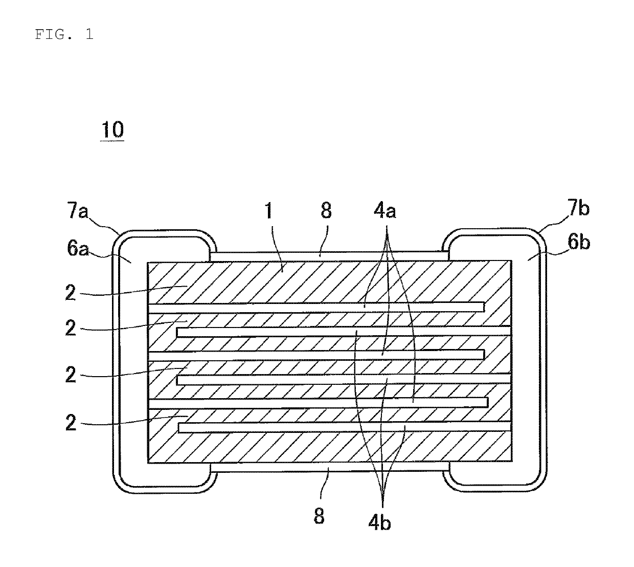
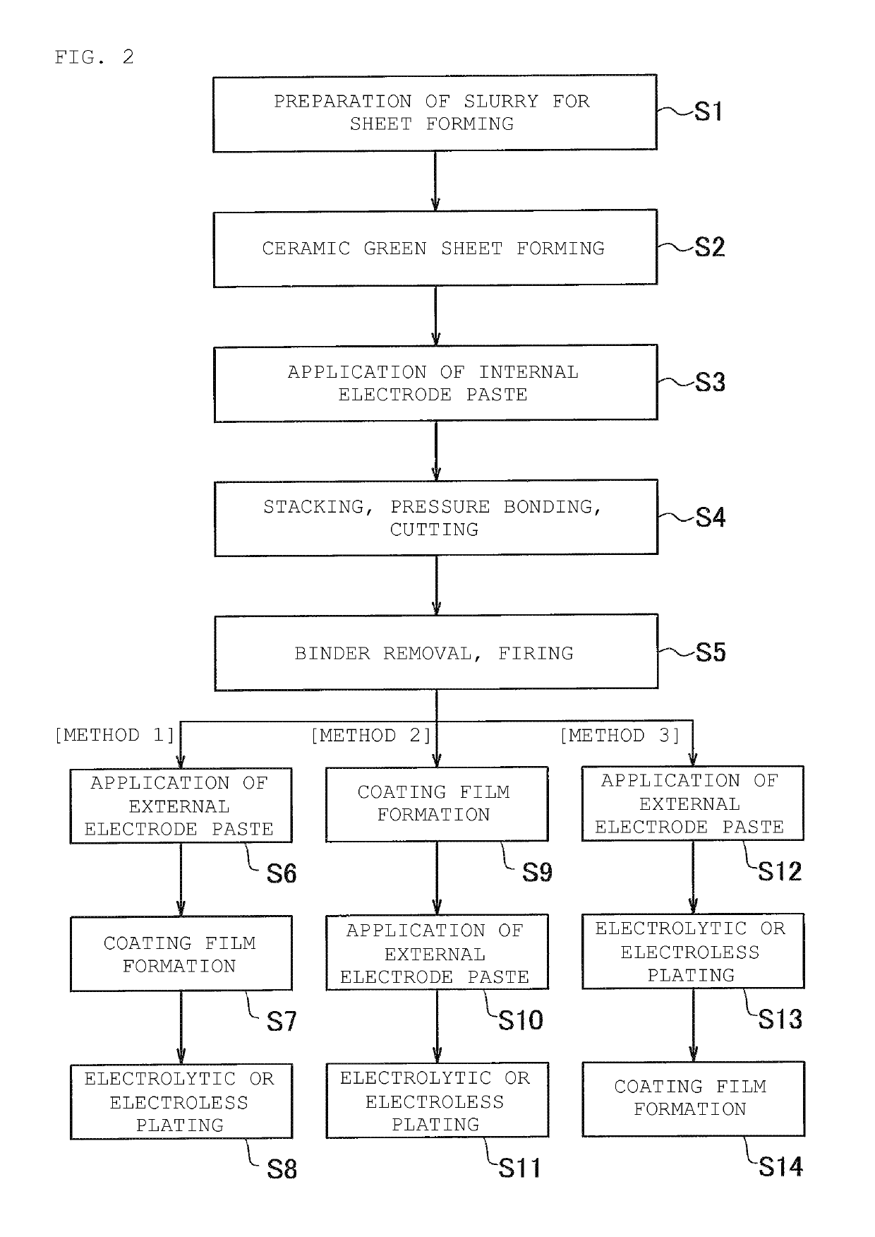
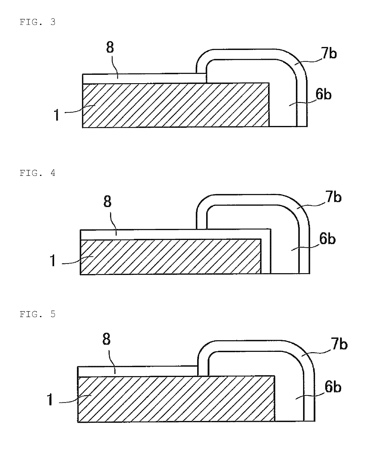
[0103]As shown in Table 1, the varistor 10 with the coating film 8 provided on the surface of the ceramic element 1 was prepared by the manufacturing method [Method 1] according to the embodiment described previously.

[0104]As the resin-containing solution, a commercially available latex of a resin component dispersed in an aqueous solvent was used with an etching promoting constituent and a surfactant added thereto, if necessary.

[0105]As the resin-containing solutions according to Examples 1 to 3, an acrylic resin (Trade Name: Nipol LX814A (from Zeon Corporation)) as the resin component was used through the adjustment of the pH to 2.0, 3.0, and 4.0 respectively with the addition of a sulfuric acid as the etching promoting constituent to the resin.

[0106]As the resin-containing solutions according to Examples 4 to 6, an acrylic resin (Trade Name: Nipol LX814A (from Zeon Corporation)) as the resin component was used through the adjustment of the pH to 2.0, 3.0, and ...

examples 15 to 39

(b) Examples 15 to 39

[0116]As shown in Table 1, multilayer ceramic capacitors (Examples 15, 20, 25, 30, and 35), laminated coils (Examples 16, 21, 26, 31, and 36), PTC thermistors (Examples 17, 22, 27, 32, and 37), NTC thermistors (Examples 18, 23, 28, 33, and 38), and LTCC substrates (Examples 19, 24, 29, 34, and 39) with the coating film provided on the surfaces of respective ceramic elements were prepared by the manufacturing method [Method 1] according to the present embodiment.

[0117]As the resin-containing solutions according to Examples 15 to 19, an acrylic resin (Trade Name: Nipol LX814A (from Zeon Corporation)) as the resin component was used through the adjustment of the pH to 3.0 with the addition of a sulfuric acid as the etching promoting constituent to the resin.

[0118]As the resin-containing solutions according to Examples 20 to 24, an acrylic resin (Trade Name: Nipol LX814A (from Zeon Corporation)) as the resin component was used through the adjustment of the pH to 3.0...


PUM

PropertyMeasurementUnit
decomposition temperatureaaaaaaaaaa
temperatureaaaaaaaaaa
heat resistanceaaaaaaaaaa

Abstract

A ceramic electronic component that includes a ceramic element, and a coating film and external electrodes that are provided on the surface of the ceramic element. The coating film is selectively formed on the surface of the ceramic element by applying, to the ceramic electronic component, a resin-containing solution containing at least one anion of a sulfuric acid, a sulfonic acid, a carboxylic acid, a phosphoric acid, a phosphoric acid, and a hydrofluoric acid.

Description

BACKGROUND OF THE INVENTION[0001]1. Field of the Invention[0002]The present invention relates to a ceramic electronic component and a method for manufacturing the component.[0003]2. Description of the Related Art[0004]The ceramics for use in electronic components may be likely to be weakened against chemical erosion by acid or alkali, and also undergo a decrease in mechanical strength of themselves, because of improvements in material due to the sophisticated functions of the electronic components.[0005]Therefore, as measures against this situation, techniques have been proposed for coating ceramic element surfaces of electronic components with resin, as described in JP 2004-500719A.[0006]Coating the ceramic element surfaces of the electronic components can reduce the influence of chemical erosion on the ceramic elements, which is caused by plating solution in the case of plating or flux in the case of mounting. Further, coating the ceramic element surfaces can, in the case of plati...

Claims


Application Information

Patent Timeline
Patent Type & Authority Patents(United States)
IPC IPC(8): H01G4/002H01C7/02H01C7/04H01C17/28H01G4/224H01G4/232C09D133/08H01F17/00H01G4/12H01G4/30C09D183/00C09D133/00C09D127/08C09D163/00C25D5/34H01C7/10H01C1/14H01G4/008C25D5/02C25D5/12C09D183/04
CPCH01G4/30C09D163/00C25D5/34H01C1/1406H01C1/1413H01C7/021H01C7/041H01C7/10H01C17/281H01F17/0033H01G4/1209H01G4/224H01G4/232C09D133/08H01G4/0085C09D183/04C25D5/022C25D5/12
Inventor INOUE, MITSUNORIMORI, TOMOHIKO
Owner MURATA MFG CO LTD
Why Eureka
Try Eureka