Mobile, climbing endless track robotic system to perform remote inspections on structures

a robotic system and remote inspection technology, applied in the direction of instruments, computing, electric digital data processing, etc., can solve the problems of increasing the cost of such inspection, posing a safety hazard to the human operator, and reducing the holding power, so as to limit the parasitic motion

Active Publication Date: 2019-06-11
BEARD JAMES +2
View PDF13 Cites 4 Cited by
  • Summary
  • Abstract
  • Description
  • Claims
  • Application Information

AI Technical Summary

Benefits of technology

[0016]The primary contribution of the invention is that it addresses the main technical challenges in creating a mobile climbing inspection system that can accommodate irregularities in the climbing surface, can distribute the climbing forces over the adhering members in an optimal fashion, and can limit parasitic motions in the inspection transducer. This invention applies to endless track-type climbing vehicles with adhering members connected to the exterior portion of the endless track. This method permits a large area of contact for the adhering members with the climbing surface. This invention addresses the drawbacks in the existing prior art through the following:1) The Inspection vehicle of this invention integrates a multi-link suspension apparatus that distributes climbing loads to maximize the system payload to weight ratio.2) The welding platform of this invention integrates a multi-link I suspension apparatus that is adaptive to irregularities in the climbing surface.3) The invention system contains a transducer manipulator that is independently suspended from the vehicle. Thus it isolates undesirable motions in the vehicle from the transducer. This lowers the control requirements on the climbing vehicle,4) The invention integrates the transducer manipulator and vehicle platform in a reconfigurable and modular arrangement to position the transducer anywhere inside, outside or around the platform, to achieve a large range of reach in inspection tasks.

Problems solved by technology

This potentially poses a safety hazard to the human operator.
It also increases the cost of such inspection due to the need for the trained operator, safety and support systems.
However, these systems tend to either place the magnets on a track without a track guide or mechanism between the end wheels (for example U.S. Pat. No. 5,884,642 or Shen and Shen, 2005) and rely on tension in the track to transfer climbing forces to the adhering members, or on a track with a rigid track guide limiting the ability to conform to a non-uniform climbing surfaces (for example U.S. Pat. No. 5,487,440, Kim et al., 2008) or a guide that has some flexibility but for purposes of pushing in a single direction on the track to make contact with the climbing surface (for example U.S. Pat. No. 4,789,037).
When climbing the loads required to maintain equilibrium are transferred to the adhering members according to the relative compliance of the carriage frame and endless track system and in general will be localized to a small number of the adhering members causing degradation in holding power.
In this regard, the technology demonstrated in the prior art suffers from a few distinct drawbacks which are discussed here.
The systems that employ magnetic wheels with axes rigidly attached to the vehicle chassis, or that attach magnets directly to the vehicle chassis lack the ability to accommodate variations in the climbing surface, and will lose adhering force and traction when traveling over surfaces that have a certain degree of geometric irregularity.
The vehicle systems that use magnetic wheels on moving axes do not demonstrate a means to distribute climbing loads among the wheels and therefore can cause the adhering forces to be localized in one or a few of the magnetic wheels.
The systems that employ endless tracks with magnets or other adhering members attached, and the endless track passing through a rigid guide attached to the vehicle frame lack the ability to accommodate variations in the climbing surface, and will lose adhering force and traction when traveling over surfaces that have a certain degree of geometric irregularity.
Systems that employ endless-tracks also can cause undesirable motions in the inspection transducer that can reduce the efficiency of inspection.
Systems that employ vacuum pressure forces for adhering rely on compliant or flexible portions of the vacuum cup (U.S. Pat. Nos. 7,520,356 and 7,076,335) or compliant surface of the endless track itself (US 2005 / 0072612 A1) to accommodate surface irregularities and enforce the perimeter seal required to maintain the vacuum forces However, the degree of surface irregularity permitted is limited by the availability and durability of the compliant materials.
In practice, engineering materials are not readily available that can accommodate large strains required by this for surfaces with significant variation.

Method used


Image

  • Mobile, climbing endless track robotic system to perform remote inspections on structures
  • Mobile, climbing endless track robotic system to perform remote inspections on structures
  • Mobile, climbing endless track robotic system to perform remote inspections on structures

Examples


Embodiment Construction

[0031]Detailed descriptions of the preferred embodiment are provided herein. It is to be understood, however, that the present invention may be embodied in various forms. Therefore, specific details disclosed herein are not to be interpreted as limiting, but rather as a basis for the claims and as a representative basis for teaching one skilled in the art to employ the present invention in virtually any appropriately detailed system, structure or manner.

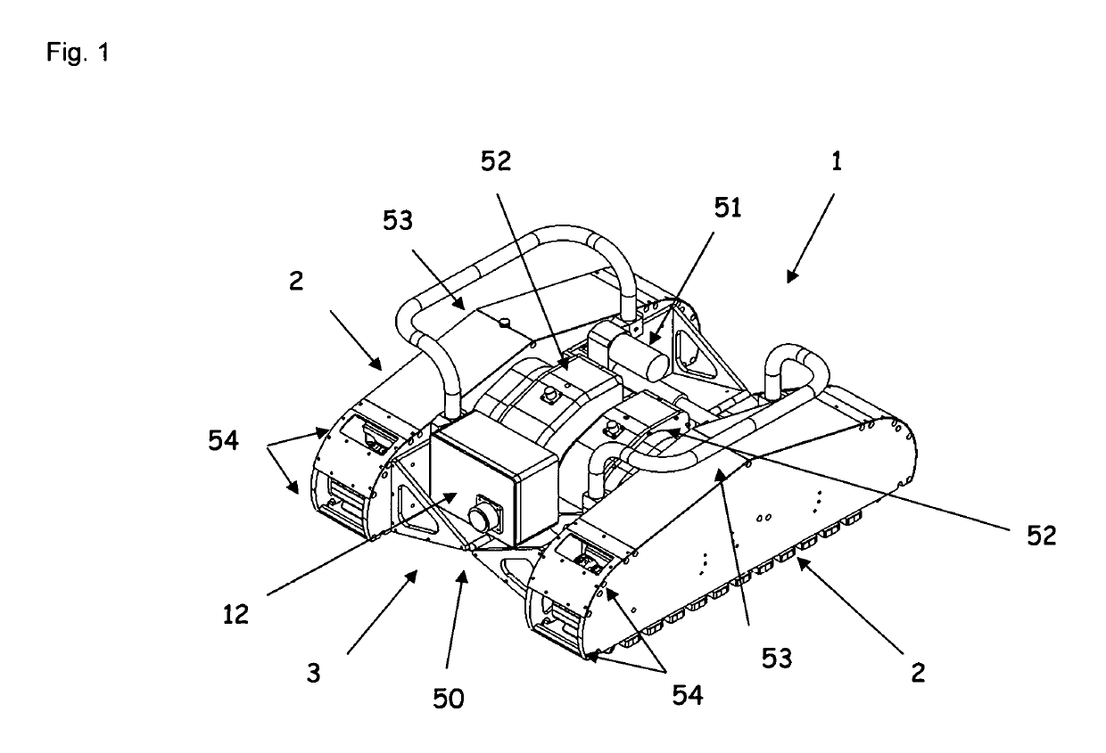
[0032]In FIG. 1, the climbing endless track vehicle (1) which comprises of one or more track units (2) connected to a chassis (3). The chassis can be a rigid member or have one or more active or passive degrees of freedom to allow some degree of relative mobility between the track units (2) to permit greater adaptation to various climbing surfaces. The chassis (3) shows a rotational degree of freedom along the longitudinal axis between the track units through the hinge (50) and actuator (51). When the chassis contains one or more deg...


PUM


Abstract

An endless-track type mobile climbing vehicle containing a suspension apparatus, transducer manipulator and surface cleaning system to perform non-destructive examination of structures while traversing the structure in all positions. The invention is able to conform to large range of irregularities of the climbing surface while maintaining contact between the track and adhering members and uniformly distributing the climbing loads on the adhering members giving the system a high payload to weight ratio. The invention is moves the inspection transducer over the surface while maintaining correct alignment of the tool relative to the surface. The invention allows an operator to perform an inspection on structures that require cleaning or other preparation prior to inspection. The invention allows an operator to perform an inspection remotely.

Description

CROSS REFERENCE TO RELATED APPLICATIONS[0001]This application claims the priority of U.S. Provisional Application Ser. No. 61 / 456,415 entitled “Mobile, climbing robotic system to perform remote inspections on ferrous structures” filed on Nov. 8, 2010, the entire contents and substance of which are hereby incorporated in total by reference.STATEMENT REGARDING FEDERALLY SPONSORED RESEARCH OR DEVELOPMENT[0002]Not ApplicableDESCRIPTION OF ATTACHED APPENDIX[0003]Not ApplicableBACKGROUND OF THE INVENTION[0004]Ferrous metal structures are commonplace in many industrial settings such as power producing plants, windmills, factories or shipyards, storage structures, buildings and bridges. These structures are often irregular and will be described as unstructured environments. Depending on the nature of the structure, periodic inspection and maintenance is required, often through standard maintenance practices. In many instances, regular inspections of these structures are required by regulato...

Claims


Application Information

Patent Timeline
Patent Type & Authority Patents(United States)
IPC IPC(8): B62D55/265B62D55/20B62D55/30B62D55/108
CPCB62D55/265B62D55/305B62D55/202B62D55/108
Inventor BEARD, JAMESCANFIELD, STEPHENGLOVSKY, STEVE
Owner BEARD JAMES
Why Eureka
Try Eureka