Internal combustion engine and oil treatment apparatus for use with the same

a technology for oil treatment apparatus and internal combustion engine, which is applied in the direction of lubricant mounting/connection, lubrication indication device, lubrication element, etc., can solve the problems of significant expenditure, engine oil degrade, and no oil treatment system, so as to prolong the oil change interval and enhance the longevity of the engine. , the effect of enhancing the longevity of the engin

Active Publication Date: 2019-06-18
KOHLER CO
View PDF17 Cites 1 Cited by
  • Summary
  • Abstract
  • Description
  • Claims
  • Application Information

AI Technical Summary

Benefits of technology

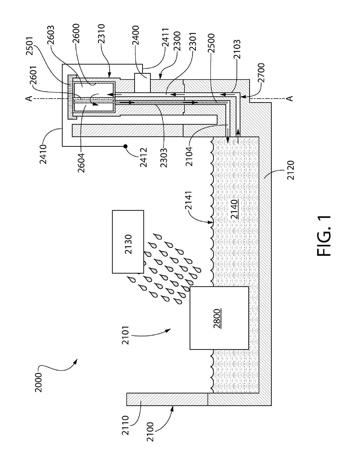
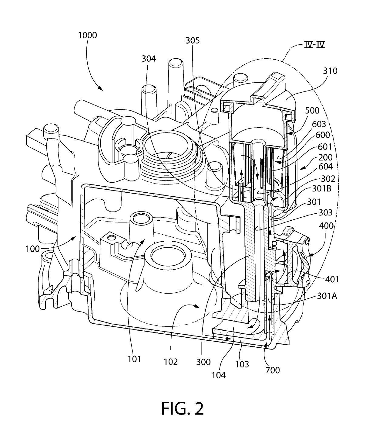
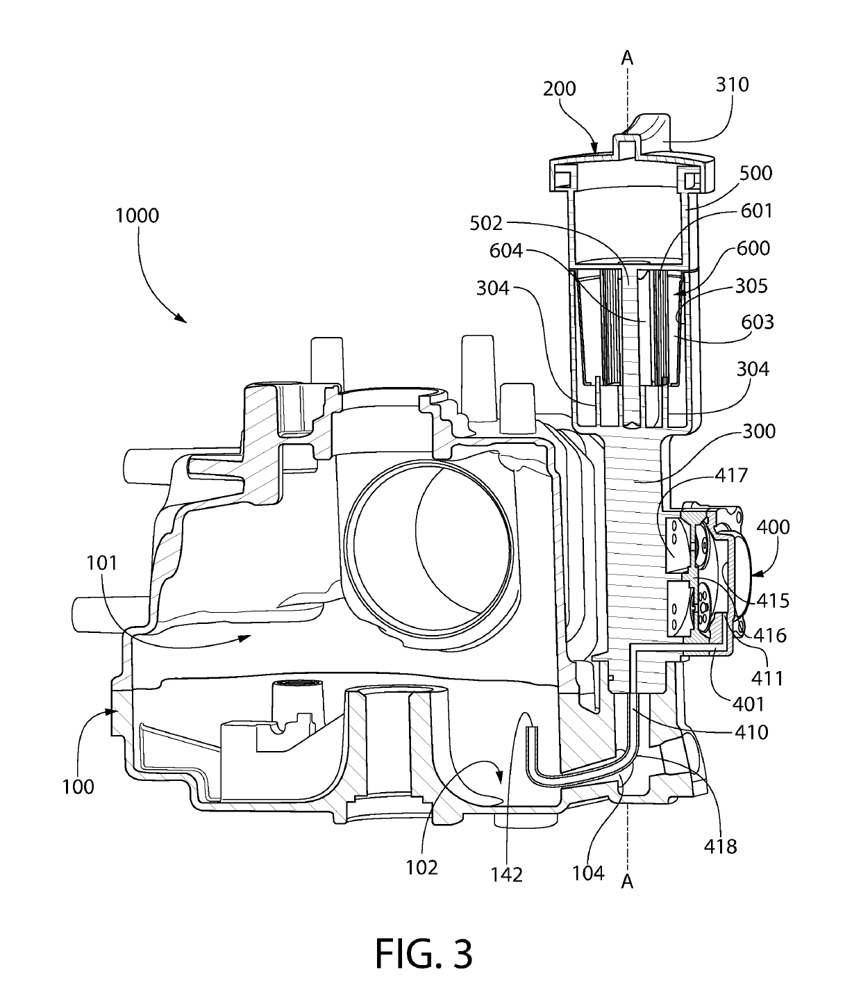
[0007]As will become apparent from the present disclosure, the inventive concepts discussed herein can be incorporated into existing splash-lubrication engine designs with minimal redesign. Furthermore, while the invention will be described herein with reference to a splash-lubrication engine, it is to be understood that the concepts disclosed herein can be utilized in engine types that include a forced flow oil filtration circuit. Moreover, the invention may be directed simply to the oil treatment apparatus itself or methods of treating oil without be limited to the engine itself and / or parts thereof. For example, it is envisioned that the invention can be directed to a sealed oil treatment apparatus that includes at least one of a filter media and / or an oil additive that can be easily inserted into an oil circulation circuit of an engine to treat the oil.
[0008]The present invention may provide a means to replenish oil additives, extend the oil change interval, and / or enhance engine longevity.

Problems solved by technology

Many splash-lubrication engines do not have an oil treatment system.
Engine oil degrades because of accumulation of wear particles, fuel, moisture, and sludge.
However, it has been generally thought that adding an oil treatment system to a splash-lubrication engine would require significant redesign of many castings, thereby resulting in a significant expenditure.

Method used


Image

  • Internal combustion engine and oil treatment apparatus for use with the same
  • Internal combustion engine and oil treatment apparatus for use with the same
  • Internal combustion engine and oil treatment apparatus for use with the same

Examples


Embodiment Construction

[0026]The following description of the preferred embodiment(s) is merely exemplary in nature and is in no way intended to limit the invention, its application, or uses.

[0027]As used throughout, ranges are used as shorthand for describing each and every value that is within the range. Any value within the range can be selected as the terminus of the range. In addition, all references cited herein are hereby incorporated by referenced in their entireties. In the event of a conflict in a definition in the present disclosure and that of a cited reference, the present disclosure controls.

[0028]The description of illustrative embodiments according to principles of the present invention is intended to be read in connection with the accompanying drawings, which are to be considered part of the entire written description. In the description of embodiments of the invention disclosed herein, any reference to direction or orientation is merely intended for convenience of description and is not ...


PUM


Abstract

An internal combustion engine having an improved oil treatment system. The internal combustion engine may be a splash lubrication engine in which oil is flowed through an oil circulation circuit by a passive pump. In another aspect, a dipstick tube may be provided that includes a portion of the oil circulation circuit. In a further aspect, the internal combustion engine comprises one or more protuberances that automatically penetrate an oil treatment apparatus upon the oil treatment apparatus being mounted to the internal combustion engine, thereby fluidly coupling the oil treatment apparatus to the oil circulation circuit.

Description

CROSS-REFERENCE TO RELATED PATENT APPLICATIONS[0001]The present application claims the benefit of U.S. Provisional Patent Application Ser. No. 62 / 205,156, filed Aug. 14, 2015, the entirety of which is incorporated by reference herein.BACKGROUND[0002]Splash-lubrication engines are generally known and widely used in small engines, such as those used in lawn mowers, outboard marine operation, lawn equipment, generators, power washers, snow blowers, and so on. In a splash lubrication engine, oil that gathers in the lower part of the crankcase, such as in the oil pan, oil tray, or other reservoir, is thrown upward as droplets (or fine mist) to provide lubrication to various parts of the engine, such as valve mechanisms, piston pins, cylinder walls, and piston rings. In one such typical splash-lubrication engine design, dippers on the connecting-rod bearing caps enter the oil trough located in the lower part of the crankcase and with each crankshaft revolution produces the oil splash. A p...

Claims


Application Information

Patent Timeline
Patent Type & Authority Patents(United States)
IPC IPC(8): F01M1/10F01M11/00F01M11/12F01M11/03F01M1/02F01M9/06
CPCF01M1/10F01M1/02F01M9/06F01M11/0004F01M11/03F01M11/12F01M1/04
Inventor ROTTER, TERRENCE M.
Owner KOHLER CO
Why Eureka
Try Eureka