Supercharge Your Innovation With Domain-Expert AI Agents!

Gyro sensor and electronic apparatus

a gyro sensor and electronic equipment technology, applied in the field of gyro sensor and electronic equipment, can solve the problems of increasing the length and amplitude of the vibrator, lowering the detection sensitivity that much, and preventing the realization of the miniaturization of the gyro sensor, so as to achieve the effect of raising the sensitivity

Inactive Publication Date: 2019-07-16
SONY CORP
View PDF15 Cites 0 Cited by
  • Summary
  • Abstract
  • Description
  • Claims
  • Application Information

AI Technical Summary

Benefits of technology

The design achieves higher sensitivity and detection accuracy for angular velocities with the same amplitude, enabling miniaturization without compromising sensitivity, by utilizing laminated piezoelectric layers and optimized electrode configurations.

Problems solved by technology

Therefore, if the gyro sensor is miniaturized, the vibration system becomes lighter to thus lower the detection sensitivity that much.
On the other hand, since an increase of the vibration velocity leads to an increase of the length and amplitude of the vibrator, it becomes an obstacle in realizing miniaturization of gyro sensors.
From all this, it has been difficult to satisfy both the high sensitivity and miniaturization in principle since those elements are contradicting.

Method used


Image

  • Gyro sensor and electronic apparatus
  • Gyro sensor and electronic apparatus
  • Gyro sensor and electronic apparatus

Examples


Embodiment Construction

[0048]Hereinafter, an embodiment of the present technology will be described with reference to the drawings.

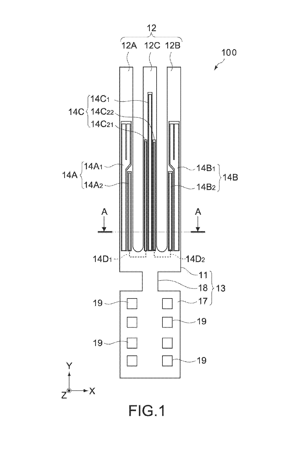
[0049]FIG. 1 is a schematic plan view showing a gyro sensor 100 according to an embodiment of the present technology. Hereinafter, a basic configuration of the gyro sensor 100 will be described.

[0050]In the figure, X-, Y-, and Z-axis directions respectively indicate three axial directions orthogonal to one another. The same holds true for the subsequent figures.

[0051](Basic Configuration of Gyro Sensor)

[0052]The gyro sensor 100 includes a coupling portion 11 and three arms 12 (12A, 12B, and 12C) that extend from the coupling portion 11 in the same direction (Y-axis direction) and each have a square-shaped cross section. The three arms 12 are aligned horizontally in the X-axis direction when seen from the Z-axis direction.

[0053]The gyro sensor 100 is configured by cutting out the coupling portion 11 and the arms 12 in a predetermined shape from a monocrystalline substrate not h...


PUM


Abstract

A gyro sensor having increased sensitivity is provided, along with an electronic apparatus including the gyro sensor. The gyro sensor includes: a vibrator; a first piezoelectric layer, and a second piezoelectric layer. The first piezoelectric layer, which includes a first electrode pair and a first piezoelectric film arranged between the first electrode pair, is arranged on a front surface of the vibrator and is capable of causing the vibrator to vibrate in a first axis direction vertical to the front surface. The second piezoelectric layer, which includes a second electrode pair and a second piezoelectric film arranged between the second electrode pair, is arranged on the first piezoelectric layer and is capable of causing the vibrator to vibrate in the first axis direction. The second piezoelectric layer functions synchronously with the first piezoelectric layer to cause the vibrator to vibrate in the first axis direction.

Description

CROSS REFERENCE TO RELATED APPLICATIONS[0001]This application is a U.S. National Stage Entry under 35 U.S.C. § 371 of International Application No. PCT / JP2015 / 001857, filed in the Japanese Patent Office on Mar. 31, 2015, which claims priority to Japanese Patent Application Number JP2014-132900, filed in the Japanese Patent Office on Jun. 27, 2014, each of which is incorporated by reference herein in its entirety.TECHNICAL FIELD[0002]The present technology relates to a gyro sensor capable of detecting an angular velocity and an electronic apparatus including the gyro sensor.BACKGROUND ART[0003]As angular velocity sensors for consumer use, vibration-type gyro sensors are widely used. The vibration-type gyro sensor detects an angular velocity by causing a vibrator to vibrate at a predetermined frequency and detecting a Coriolis force caused in the vibrator using a piezoelectric device and the like. The gyro sensors are mounted on electronic apparatuses such as a video camera, a virtual...

Claims


Application Information

Patent Timeline
Patent Type & Authority Patents(United States)
IPC IPC(8): H01L41/09H01L41/04H01L41/297H01L41/113B06B1/06G01C19/5621G01C19/5628H10N30/00H10N30/067H10N30/20H10N30/30H10N30/80H10N30/87
CPCG01C19/5621B06B1/0611B06B1/0622H01L41/297H01L41/042H01L41/094H01L41/1132G01C19/5628H10N30/302H10N30/067H10N30/802H10N30/2042
Inventor HONDA, JUNICHI
Owner SONY CORP
Features
  • R&D
  • Intellectual Property
  • Life Sciences
  • Materials
  • Tech Scout
  • Unparalleled Data Quality
  • Higher Quality Content
  • 60% Fewer Hallucinations
Learn More