Fuel treatment module, system and method

a fuel treatment module and fuel treatment technology, applied in the direction of combustion air/fuel air treatment, machines/engines, mechanical equipment, etc., can solve the problems of system inability to achieve photon saturation, limited in the amount of far infrared treatment that can be applied to the volume of fuel, etc., to achieve easy connection, improve fuel efficiency, and reduce emissions

Active Publication Date: 2019-08-06
CAMERON DYNAMICS LLC
View PDF19 Cites 1 Cited by
  • Summary
  • Abstract
  • Description
  • Claims
  • Application Information

AI Technical Summary

Benefits of technology

[0007]A fuel treatment module, system and method for treating fuel to improve fuel efficiency and lower emissions are disclosed herein. As will be detailed further below, the infrared (IR) emitting fuel treatment module may have a variety of configurations and is capable of operating in various environments of use, including mobile and fixed environments. In addition, the fuel treatment module may be used to treat various types of hydrocarbon fuel, and may be easily connected to additional fuel treatment modules to increase fuel treatment capacity. Compared to conventional fuel treatment devices, the fuel treatment module provides the structure and method for treating a larger amount of fuel in a shorter time frame or treating fuel in systems that have a higher flow rate by reducing the incoming fuel's flow rate and routing the fuel both inside and outside the far infrared emitting substance.

Problems solved by technology

However, the fuel flows through the fuel line too quickly for effective treatment by the far infrared emissions, so cannot achieve photon saturation.
Though various systems have been designed to treat fuel with far-infrared radiation, these conventional systems do not achieve photon saturation, but are limited in the amount of far infrared treatment that can be applied to the volume of fuel in the time available for treatment.

Method used


Image

  • Fuel treatment module, system and method
  • Fuel treatment module, system and method
  • Fuel treatment module, system and method

Examples


Embodiment Construction

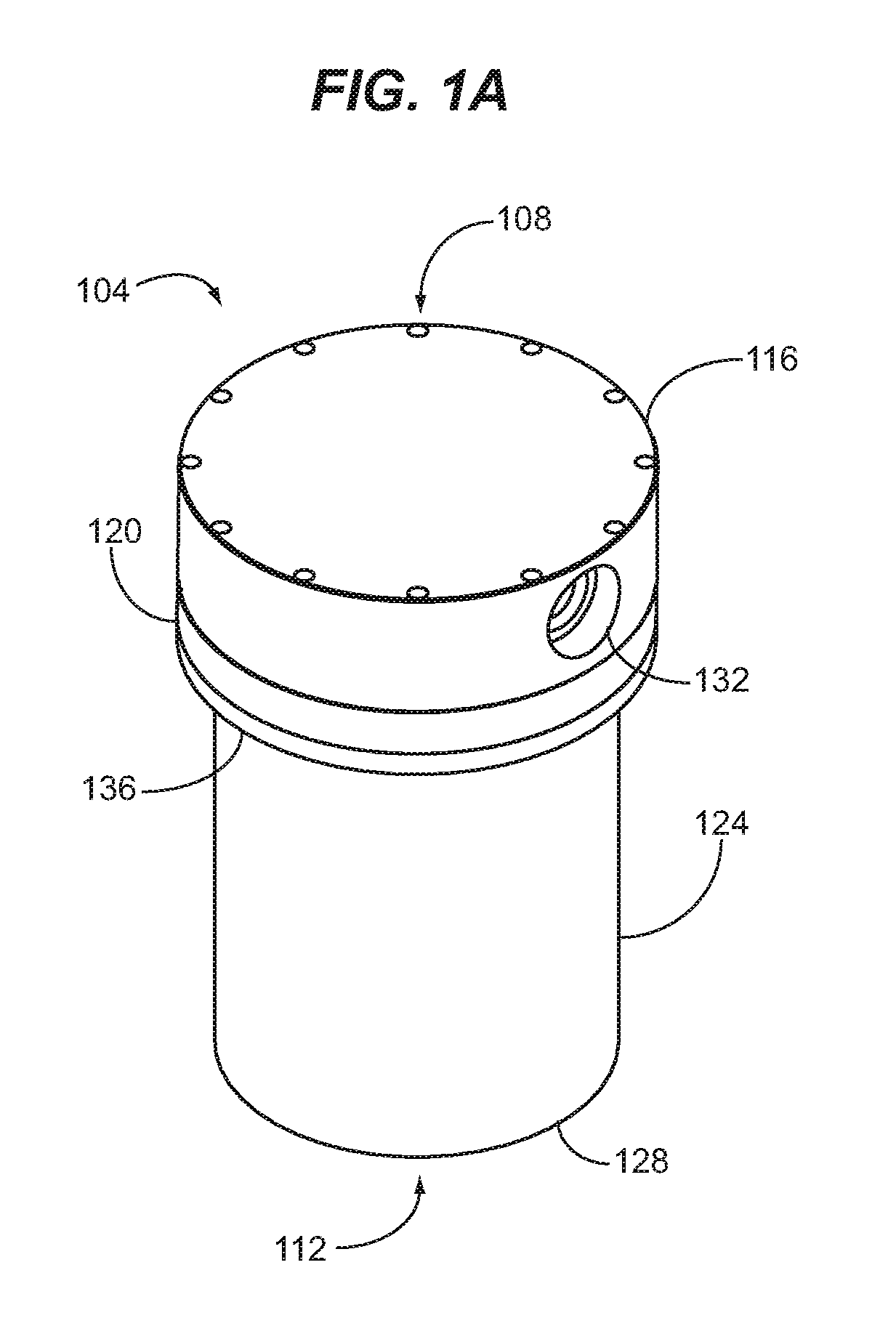
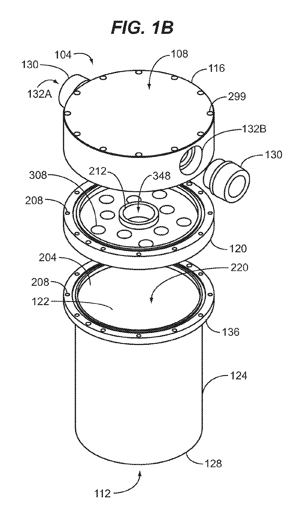
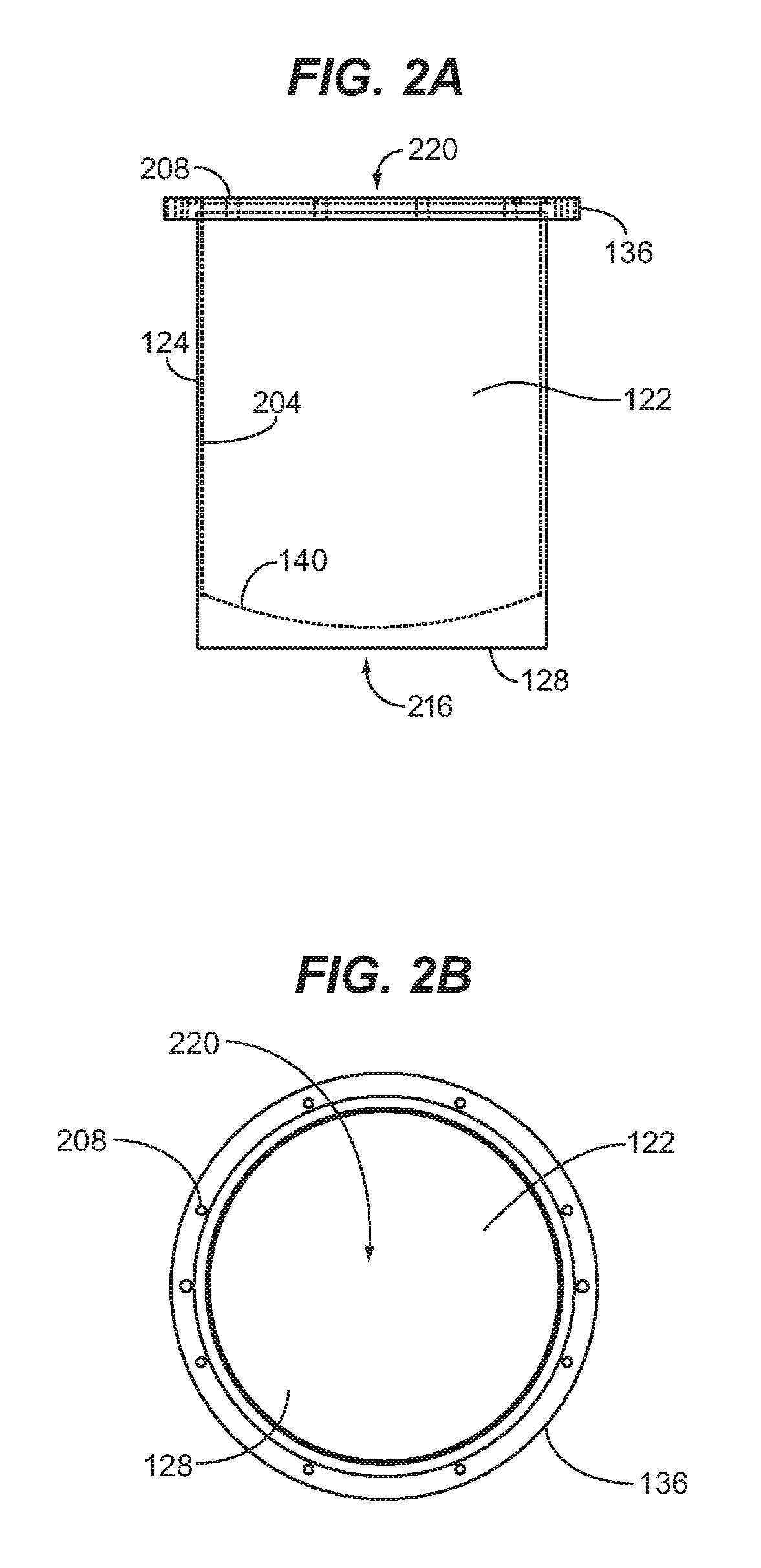
[0031]The fuel treatment module 104 herein benefits from the property of liquid substances, such as liquid hydrocarbon fuel, that when an infrared emitting element 320 (FIGS. 3, 4, 5, 10A-10F) is brought close to such liquid substances, the infrared radiation (in the form of photons) emitted from the infrared emitting element 320 is absorbed by molecules in the liquid, transferring energy to the molecules and exciting them. (Hydrocarbon molecules in fuel are capable of utilizing the infrared radiation between 3 and 20 μm (micron) wavelengths to cause such excitation of the fuel.) The fuel treatment module 104 herein employs a plurality of infrared emitting elements 320, which in a preferred embodiment are infrared emitting ceramic elements, designed to emit infrared radiation at 3 to 20 μm wavelengths that are disposed within a canister 124. The canister 124 and its internal components both facilitate and maximize direct and indirect exposure of fuel to the infrared emitting element...


PUM

PropertyMeasurementUnit
wavelengthsaaaaaaaaaa

Abstract

A fuel treatment module treats fuel with infrared radiation from a plurality of infrared radiation emitting elements arranged in a structure configured to ensure sufficient exposure of the fuel to infrared radiation. Such structure includes a head cap and spacer having through bores providing a manifold through which fuel flows into multiple IR/shunt columns of infrared radiation emitting elements that are disposed within a canister. Then the fuel moves out of the multiple IR/shunt columns into the open area of the canister where the fuel then flows around the exterior of the columns, exposing the fuel to further infrared radiation treatment.

Description

CROSS-REFERENCE TO RELATED APPLICATIONS[0001]This nonprovisional application claims the benefit of U.S. Provisional Patent Application Ser. No. 62 / 427,713, filed on Nov. 29, 2016, which is incorporated herein in its entirety.FIELD OF THE INVENTION[0002]The invention relates to hydrocarbon fuel treatment systems and methods and, more particularly, to a hydrocarbon fuel treatment module for maximizing exposure of fuel to active infrared treatment elements.BACKGROUND OF THE INVENTION[0003]A variety of systems and methods have been developed to treat fuel to improve characteristics thereof. U.S. Pat. No. 7,281,526 by Keiichiro discloses a fuel-improving device that applies far-infrared radiation to fuel by placing granular far-infrared emitting substances directly in the flow path of fuel to improve output power and fuel economy of an internal combustion engine. The inlet and outlet of the device have a porous structure having pores sized to prevent the far-infrared emitting granules fr...

Claims


Application Information

Patent Timeline
Patent Type & Authority Patents(United States)
IPC IPC(8): F02M27/06C10L1/04B01J8/22F02M33/08
CPCF02M27/06F02M33/08C10L1/04B01J8/226B01D2273/22C10G32/04
Inventor GROVATT, WILLIAM RICHARDVIHONSKI, RICHARD MICHAELMESKO, THOMAS D.
Owner CAMERON DYNAMICS LLC
Why Eureka
Try Eureka