
Cement clinker line and a method for operating a cement clinker line

a cement clinker and cement clinker technology, which is applied in the direction of gas treatment, membrane technology, dispersed particle separation, etc., can solve the problems of unsuitable hot gas dedusting, unsatisfactory hot gas dedusting, and potential misinformation, so as to reduce operating costs

Active Publication Date: 2019-08-27
SUDBAYERISCHES PORTLAND ZEMENTWERK GEBR WIESBOCK & CO
View PDF6 Cites 0 Cited by
  • Summary
  • Abstract
  • Description
  • Claims
  • Application Information

AI Technical Summary

Benefits of technology

[0010]Implementations of the invention solve the problem of reduction of mercury emissions and, at least in part, emissions of other heavy metal from a cement clinker line at reduced operating costs.
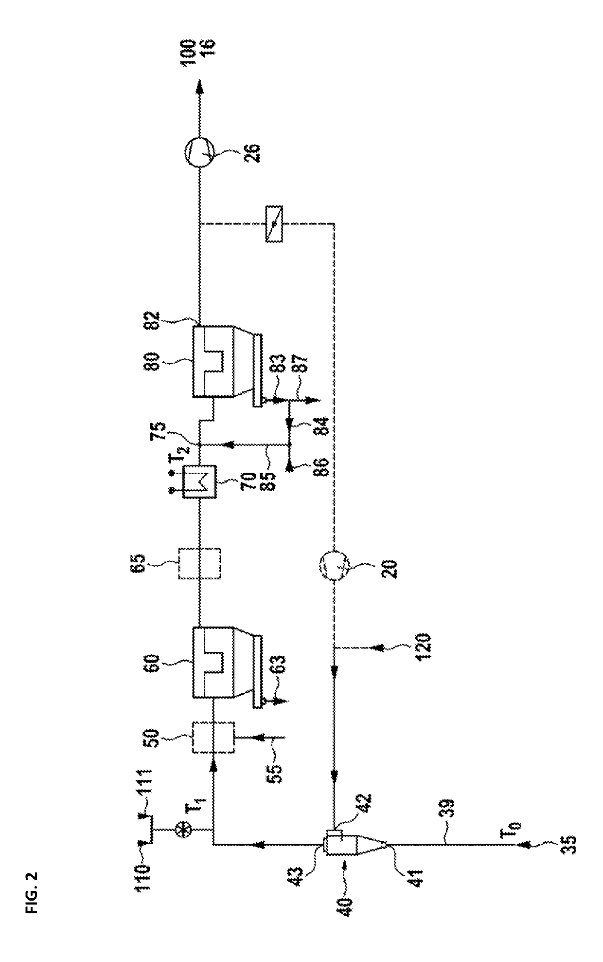
[0011]The idea of the invention stems from the observation that heavy metal emissions (such as, for example, mercury emissions) are low during the ramp up of the process. It thus appears that the mercury has to accumulate in the cement clinker line before it leaves the process via the exhaust. According to the idea of the invention, it is thus sufficient to maintain a low mercury concentration in the cement clinker line to reduce mercury emissions via the exhaust gas. This approach applies accordingly to reduce other heavy metal emissions.

Problems solved by technology

While the related term ‘gasification’ can be also used in this situation, such related term is typically used only for converting hydrocarbon fuels to carbon monoxide and could thus be potentially misleading.
Moreover, if fresh air is used to cool the bypass gas to condense the chlorides, undesired oxygen is inevitably added to the bypass gas.
Bag filters for example are cheap but not suited for dedusting hot gases.

Method used


Image

  • Cement clinker line and a method for operating a cement clinker line
  • Cement clinker line and a method for operating a cement clinker line

Examples


Embodiment Construction

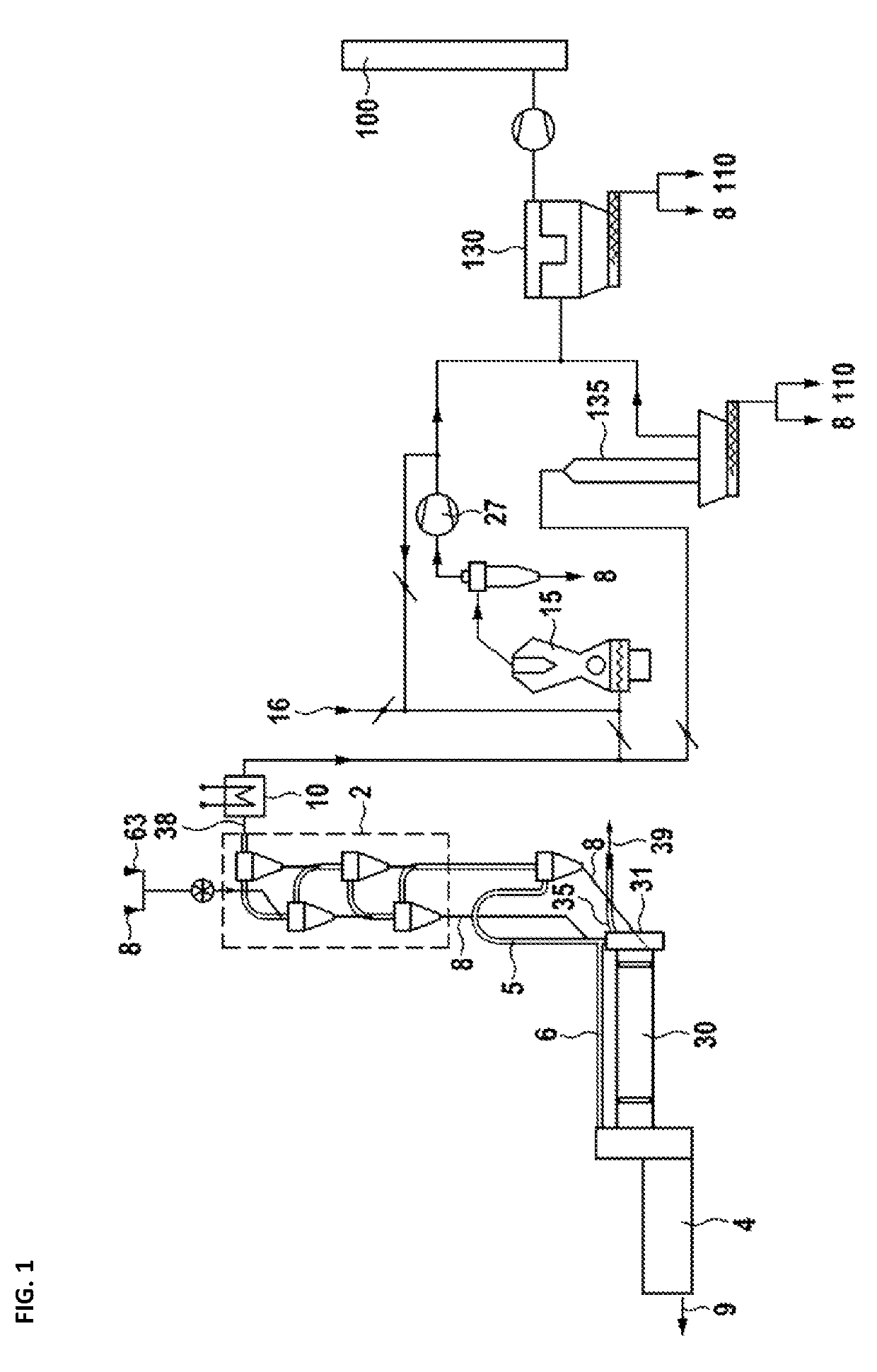
[0037]The cement clinker line in FIG. 1 comprises as usual a preheater 2, a kiln 30 and a clinker cooler 4. Raw meal 8 is preheated in the preheater 2 and provided to the kiln inlet 31. In the kiln 30 the raw meal 8 is calcined and sintered to clinker. The clinker 9 is discharged on the clinker cooler 4 and can be further processed after being cooled down (indicated by an arrow, symbolizing the clinker 9), e.g. by milling. Hot air from the clinker cooler 4 is provided to the kiln 30 as secondary air and leaves the kiln 30 at its inlet 31 as flue or exhaust gas. Said kiln exhaust gas is dust loaded and hot (typically 1500° C. to 2000° C.). The main amount of the kiln exhaust gas (briefly flue gas) is provided to the preheater 2 configured for pre-warming the raw meal 8. Optionally, a calciner 5 may be installed between the preheater 2 and the kiln 30. In that case the raw meal 8 is provided from the preheater 2 to the calciner 5 and from the calciner 5 to the kiln 30. At least a part...


PUM

PropertyMeasurementUnit
temperature T1aaaaaaaaaa
boiling temperatureaaaaaaaaaa
temperatureaaaaaaaaaa

Abstract

A method for manufacturing clinker includes sintering raw meal in a kiln to clinker, preheating the raw meal (prior to sintering the raw meal) in a preheater using a main flue gas stream from the kiln as heat source, dedusting the main flue gas downstream of the preheater at a temperature below the boiling point of mercury (thereby obtaining mercury loaded dust) and withdrawing a bypass flue gas stream from the kiln. The method is configured to efficiently remove mercury from the manufacturing process if mercury in the bypass flue gas is vaporized by injecting of at least a fraction of the mercury-loaded dust into the bypass flue gas stream. Subsequently, the bypass flue gas is dedusted and cooled down. Thereby, the mercury can be adsorbed by injecting an adsorbent (such as activated charcoal) into the bypass flue gas. With subsequent removal of the adsorbent, mercury is finally removed from the manufacturing process.

Description

CROSS-REFERENCE TO RELATED APPLICATIONS[0001]This application is a continuation of the pending International Application No. PCT / EP2017 / 056415 filed on 17 Mar. 2017, which designates the United States and claims priority from the European Application No. 16161105.8 filed on 18 Mar. 2016. The disclosure of each of the above-identified applications is incorporated by reference herein.BACKGROUND1. Field of the Invention[0002]The invention relates to a method for manufacturing cement clinker by sintering raw meal in a kiln to cement clinker (interchangeably referred to as clinker, for short). To this end raw meal is preheated in a preheater system or tower (interchangeably referred to as preheater) with the use of a main flue gas stream from the kiln as heat source. Downstream from the preheater, the flue gas is cooled to a temperature below that corresponding to the boiling point of mercury and dedusted, thereby obtaining mercury-loaded dust. A bypass flue gas stream is withdrawn from ...

Claims


Application Information

Patent Timeline
Patent Type & Authority Patents(United States)
IPC IPC(8): C04B2/10C04B7/60C04B7/36B01D53/64B01D53/02C04B7/44C04B28/04C04B9/12C04B32/00C04B28/00C04B7/34C04B7/00
CPCC04B7/44C04B7/364B01D53/02B01D53/64B01D2257/602B01D2258/0233C04B7/60
Inventor LEIBINGER, HELMUT
Owner SUDBAYERISCHES PORTLAND ZEMENTWERK GEBR WIESBOCK & CO
Learn More