System and method for dynamically locating a fault observed on a component

a technology of dynamic locating and fault observation, applied in the field of forging, can solve the problems of rejecting these components, affecting the good diagnosis of defects, and not being able to analys

Active Publication Date: 2019-08-27
SN DETUDE & DE CONSTR DE MOTEURS DAVIATION S N E C M A
View PDF11 Cites 2 Cited by
  • Summary
  • Abstract
  • Description
  • Claims
  • Application Information

AI Technical Summary

Problems solved by technology

At the time of shaping forged components, fluctuation in production may lead to the forming of defects potentially causing the rejection of these components.
The cause of a defect may be related to forging parameters or to faulty configuration of forming tools.
In addition, with this type of comparison it is not possible to locate a defect generated during an intermediate forging step and it is not possible to analyse propagation of the defect, which is detrimental to good diagnosis of defects.

Method used


Image

  • System and method for dynamically locating a fault observed on a component
  • System and method for dynamically locating a fault observed on a component
  • System and method for dynamically locating a fault observed on a component

Examples


first embodiment

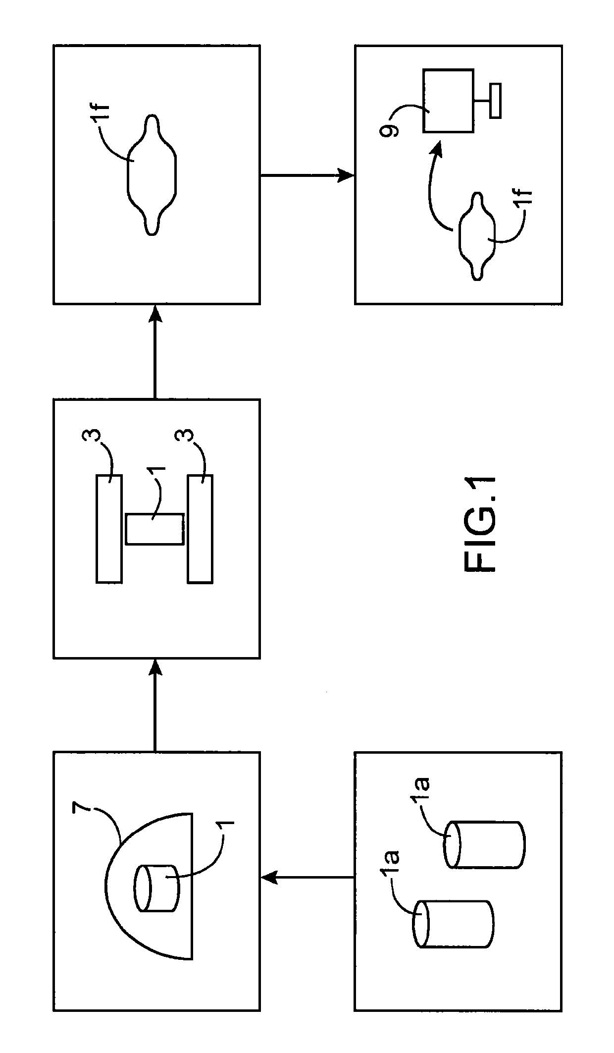
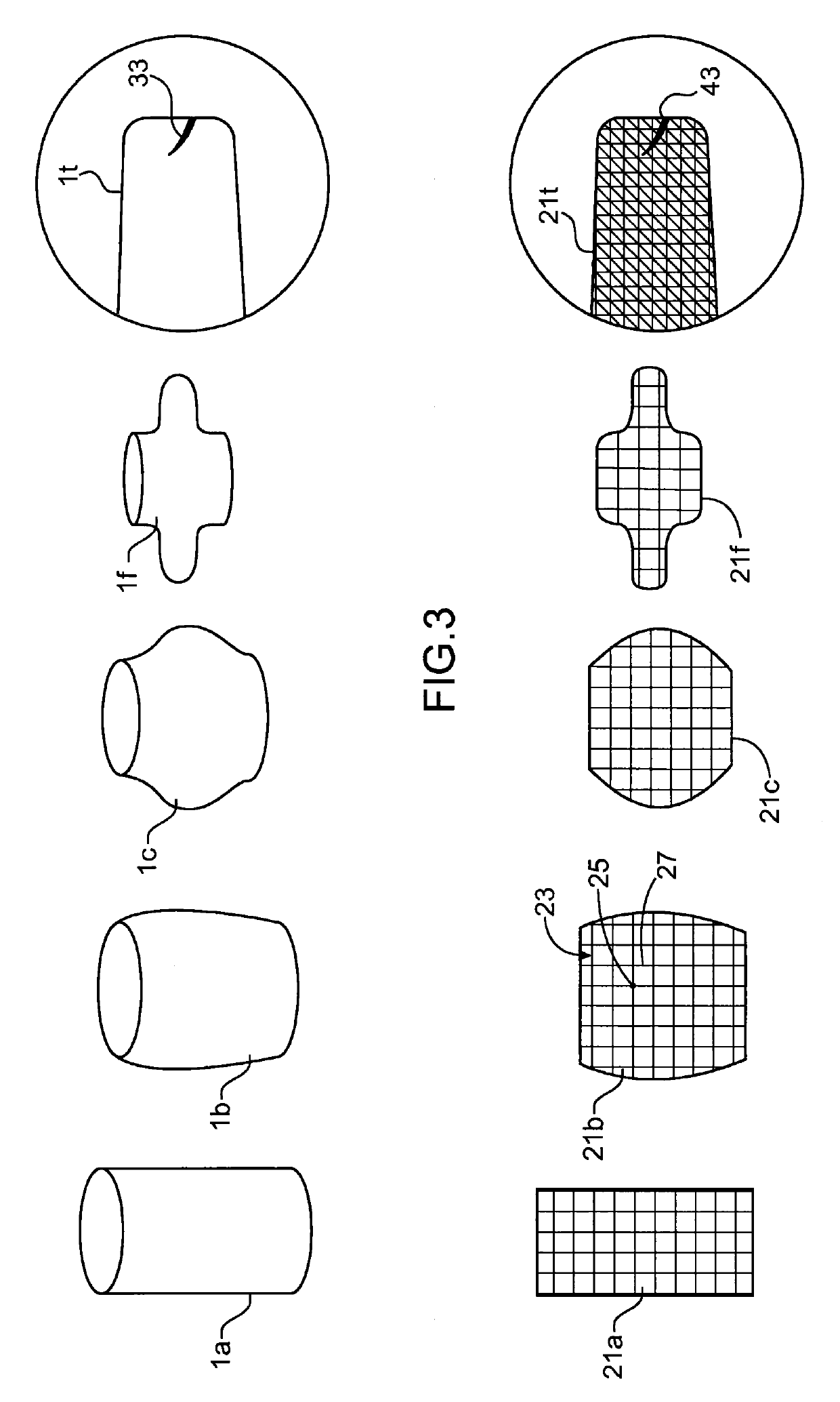
[0015]According to the present invention, the said set of successive models comprises an initial model corresponding to the component before forging, intermediate models corresponding to intermediate forging steps, and a final model corresponding to the forged component, the said first model corresponding to the said final model and the first plotted model corresponding to a final plotted model, the processing means being configured to track the said fault plotter in time by reversing the sequence of the said modelling starting from the said final plotted model.

[0016]The processing means are configured to locate the said fault plotter in the initial model to identify the region in which the fault would have been in the component before forging.

[0017]Advantageously, the processing means are configured to locate the said fault plotter in intermediate models comprising particular configurations to verify whether the said particular configurations are likely to induce the said fault.

second embodiment

[0018]According to the present invention, the said set of successive models comprises an initial model corresponding to the component before forging and a final model corresponding to the forged component, the said first model corresponding to the said initial model and the said first plotted model corresponding to an initial plotted model, the processing means being configured to locate the said fault plotter in the final model to verify whether the fault in the forged component lies outside a machining region of the said forged component.

[0019]Advantageously, the said fault plotter is a contrast element associated with the said polygonal mesh.

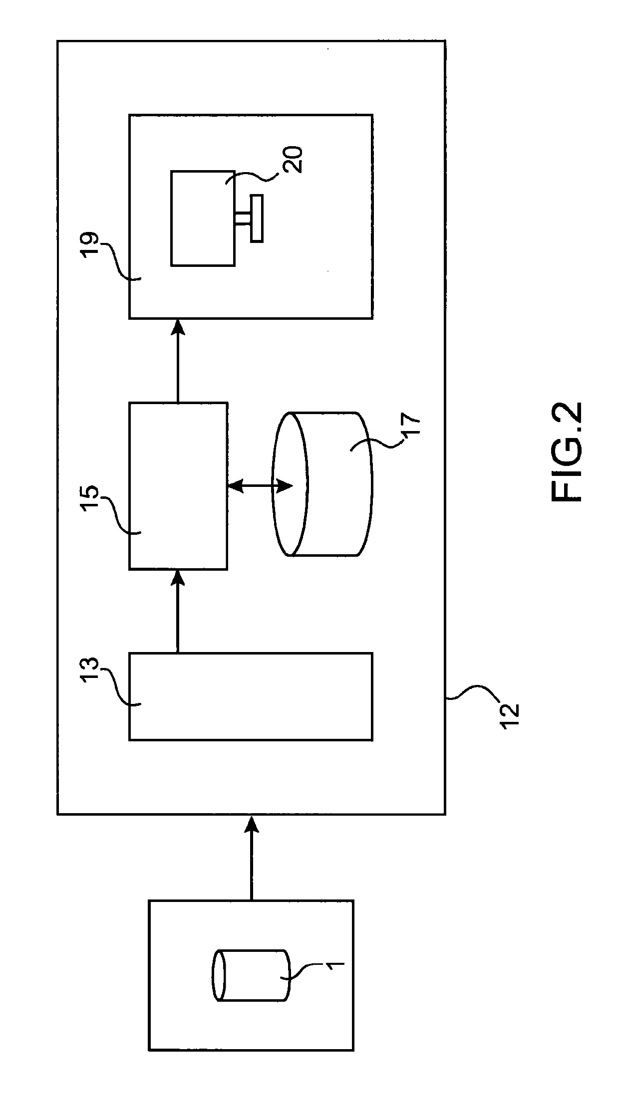
[0020]The invention also concerns a method for the dynamic locating of a fault observed in a defective component related to a forging operation, comprising the following steps:[0021]modelling an operation to shape a component by forging as per a set of successive models of the said component;[0022]adding a fault plotter, to a first model of s...


PUM

PropertyMeasurementUnit
temperatureaaaaaaaaaa
dimensionsaaaaaaaaaa
ultrasoundaaaaaaaaaa

Abstract

A method and system for dynamic locating of a fault observed in a defective component related to a forging operation, in which: a processor models a shaping operation of a component by forging, as per a set of successive models of the component; a processor adds a fault plotter to a first model of the set of models, in a zone corresponding to a region of the fault in the defective component to obtain a first plotted model; and a processor tracks the plotter in time from the first plotted model during the modelling to locate an origin of the fault.

Description

TECHNICAL FIELD[0001]The present invention relates to the general field of forging and concerns the dynamic locating of a fault found in a defective component resulting from the forging operation. It finds application in all industrial fields and in particular in the field of aeronautics in which forged components are subjected to maximum constraints of quality and safety.STATE OF THE PRIOR ART[0002]At the time of shaping forged components, fluctuation in production may lead to the forming of defects potentially causing the rejection of these components. The detection of defects in forged components can be performed using inspection means of ultrasound, magnetic detection or visual type.[0003]The cause of a defect may be related to forging parameters or to faulty configuration of forming tools. It is therefore important to identify or locate the origin of a defect to improve the forging operation or tooling.[0004]At the current time, to identify the origin of a defect in a forged co...

Claims


Application Information

Patent Timeline
Patent Type & Authority Patents(United States)
IPC IPC(8): B21J5/00G01N29/44G06T7/00G01N29/04G01N33/20
CPCB21J5/00G01N29/043G01N29/4472G01N2291/0251G06T7/001G06T2207/30136G06T2207/30164B21J5/06G01N21/95G01N29/04G01N29/44G06T7/00G01N33/20
Inventor LEBLANC, JONATHAN
Owner SN DETUDE & DE CONSTR DE MOTEURS DAVIATION S N E C M A
Why Eureka
Try Eureka