EPR systems for flow assurance and logging

a technology of flow assurance and logging, applied in the direction of instruments, nmr measurement, borehole/well accessories, etc., can solve the problems of unsuitable epr spectrometers for use in wells or pipelines, heavy weight and physical dimensions, and high cost of components

Active Publication Date: 2019-09-10
RICE UNIV
View PDF13 Cites 1 Cited by
  • Summary
  • Abstract
  • Description
  • Claims
  • Application Information

AI Technical Summary

Benefits of technology

[0005]In one embodiment, components of an EPR spectrometer may comprise a transceiver, a magnetic field generator with adjustable magnetic field, and a loop-gap resonator. In some embodiments, the EPR spectrometer may be positioned adjacent to a window of a pipeline. Further, the magnetic field generator may produce a magnetic field, more particularly a DC magnetic field. The magnetic field generator may comprise magnets, coils, or a combination thereof that are positioned outside or inside of the pipeline to generate a magnetic field. A transceiver of the EPR spectrometer may provide a pulsed or continuous signal to a resonator to generate a pulsed or continuous RF magnetic field approximately normal to a DC magnetic field of the magnets or coils. A receiver of the EPR spectrometer may monitor the reflected signal to detect changes in reflected signal. The changes in the reflected signal may be analyzed to determine the materials present, material concentrations, and their location in the pipeline. This may allow for realtime detection of asphaltenes, heptane, wax, other deposits, and combinations thereof.
[0006]In another embodiment, the EPR spectrometer may be positioned adjacent to a window in a downhole or logging tool that is suitable for placement in a wellbore. Magnets, coils, or a combination thereof may be positioned outside or inside of the logging tool to generate a magnetic field. A transceiver of the EPR spectrometer may provide a pulsed or continuous signal to a resonator to generate a pulsed or continuous RF magnetic field approximately normal to a DC magnetic field of the magnets or coils. A receiver of the EPR spectrometer may monitor the reflected signal to detect changes in reflected signal. The changes in the reflected signal may be analyzed to determine the materials present, material concentrations, and their location in the wellbore. This may allow for realtime detection of hydrocarbons, heavy oil, makeup of the formation, asphaltenes, and combinations thereof.

Problems solved by technology

EPR spectrometers comprise components that are expensive, heavy, and large in weight and physical dimensions.
Because of the high cost ($500 k), large size (1 m3), and large weight (100 kG) of EPR spectrometers, EPR spectrometers are unsuitable for use in wells or pipelines.

Method used


Image

  • EPR systems for flow assurance and logging
  • EPR systems for flow assurance and logging
  • EPR systems for flow assurance and logging

Examples


experimental example

[0043

[0044]The following examples are included to demonstrate particular aspects of the present disclosure. It should be appreciated by those of ordinary skill in the art that the methods described in the examples that follow merely represent illustrative embodiments of the disclosure. Those of ordinary skill in the art should, in light of the present disclosure, appreciate that many changes can be made in the specific embodiments described and still obtain a like or similar result without departing from the spirit and scope of the present disclosure.

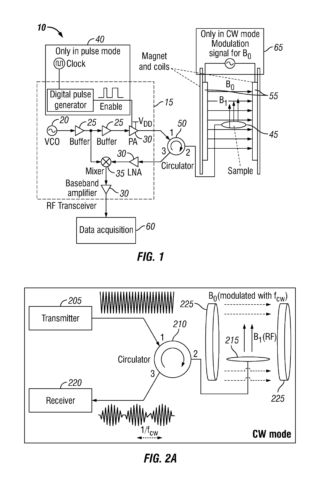
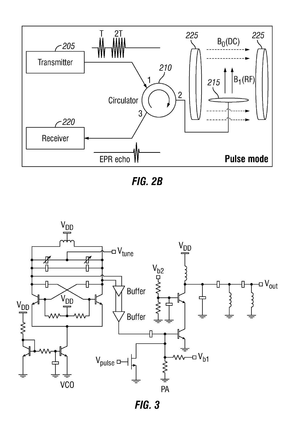
[0045]The integrated EPR spectrometer was tested using ˜50 mg of 2,2-Diphenyl-1-Picrylhydrazyl (DPPH) powder at room temperature. The Zeeman field is set to around 340 G (0.034 T), corresponding to 950 MHz absorption frequency. This frequency of operation is chosen as a compromise: lower frequencies would result in lower SNR, yet at higher frequencies generating magnetic fields for portable systems would be problematic. The RF signal is...


PUM

PropertyMeasurementUnit
weightaaaaaaaaaa
frequenciesaaaaaaaaaa

Abstract

An Electron Paramagnetic resonance (EPR) system and method allows the measurement paramagnetic characteristics of materials in real-time, such as heavy oil, hydrocarbons, asphaltenes, heptane, vanadium, resins, drilling fluid, mud, wax deposits or the like. The EPR systems and methods discussed herein are low cost, small and light weight, making them usable in flow-assurance or logging applications. The EPR sensor is capable of measuring paramagnetic properties of materials from a distance of several inches. In some embodiments, a window will be used to separate the EPR sensor from the materials in a pipeline or wellbore. Since the sensor does need to be in direct contact with the materials, it can operate at a lower temperature or pressure. In other embodiments, the EPR sensor may be placed in the materials.

Description

CROSS-REFERENCE TO RELATED APPLICATIONS[0001]This application claims priority to U.S. Provisional Patent Application No. 61 / 882,296, filed on Sep. 25, 2013. The entirety of the aforementioned application is incorporated herein by reference.FIELD OF THE INVENTION[0002]This invention relates to methods and systems utilizing electron paramagnetic resonance (EPR) to detect the characteristics of materials. More particularly, to utilizing EPR systems or methods to detect the characteristics of materials in wells, pipelines or formations, such as for flow assurance or logging.BACKGROUND OF INVENTION[0003]Electron paramagnetic resonance (EPR) phenomenon is based on interaction of electron spins with electromagnetic fields in the presence of an external DC magnetic field. EPR data provides valuable information about electronic structures and spin interactions in paramagnetic materials. EPR has found wide-ranging applications in various science and engineering technology areas, such as study...

Claims


Application Information

Patent Timeline
Patent Type & Authority Patents(United States)
IPC IPC(8): G01V3/32G01R33/60E21B49/08G01R33/36G01N24/10G01V3/26G01R33/44G01R33/381
CPCG01N24/10E21B49/08G01R33/3607G01R33/3621G01V3/26G01V3/32G01R33/60G01R33/448E21B2049/085G01R33/381E21B49/0875
Inventor BABAKHANI, AYDINYANG, XUEBEI
Owner RICE UNIV
Why Eureka
Try Eureka