
Composite propeller blade for an aircraft

a propeller blade and composite technology, applied in the field of aircraft propeller blades, can solve the problems of affecting the mechanical strength of the blade, and unable to keep the shaping portion in the reference position inside the densified fiber structure, etc., and achieve the effect of increasing the mechanical strength

Active Publication Date: 2019-09-17
SN DETUDE & DE CONSTR DE MOTEURS DAVIATION S N E C M A
View PDF11 Cites 7 Cited by
  • Summary
  • Abstract
  • Description
  • Claims
  • Application Information

AI Technical Summary

Benefits of technology

The patent describes an aircraft propeller blade design that improves its mechanical strength. Specifically, it provides a retaining portion in the rear edge of the blade that holds the shape of the spar in place within the fiber structure of the blade. This prevents the spar from moving in position, even during mechanical stresses or impacts on the blade. Ultimately, this design ensures that the blade is more durable and resistant to damage.

Problems solved by technology

Although propeller blades made of metal material present good strength, they nevertheless present the drawback of being relatively heavy.
Nevertheless, in certain circumstances, such as for example when the blade is subjected to high levels of mechanical loading, to impacts, or to shocks, keeping the shaping portion in its reference position inside the densified fiber structure can be difficult, in particular at the rear edge of the fiber structure which is of reduced strength because of the presence of non-interlinking at this location in the fiber structure.

Method used


Image

  • Composite propeller blade for an aircraft
  • Composite propeller blade for an aircraft
  • Composite propeller blade for an aircraft

Examples


Embodiment Construction

[0035]The invention applies in general to various types of propeller for use with engines for aircraft such as airplanes or helicopters. An advantageous but non-exclusive application of the invention lies in propellers of large dimensions that, because of their size, present considerable weight having a significant impact on the overall weight of an aeroengine.

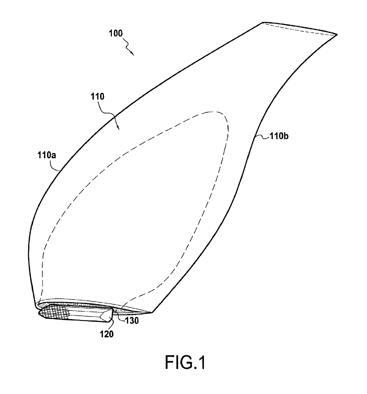
[0036]FIG. 1 shows a propeller blade 100 for mounting on an airplane turboprop, which blade comprises a streamlined structure 110 that is to form the airfoil of the blade, a root 120 formed by a portion of greater thickness, e.g. having a bulb-shaped section extended by a tang 130. In cross-section, the streamlined structure 110 presents a curved profile of thickness that varies between its leading edge 110a and its trailing edge 110b.

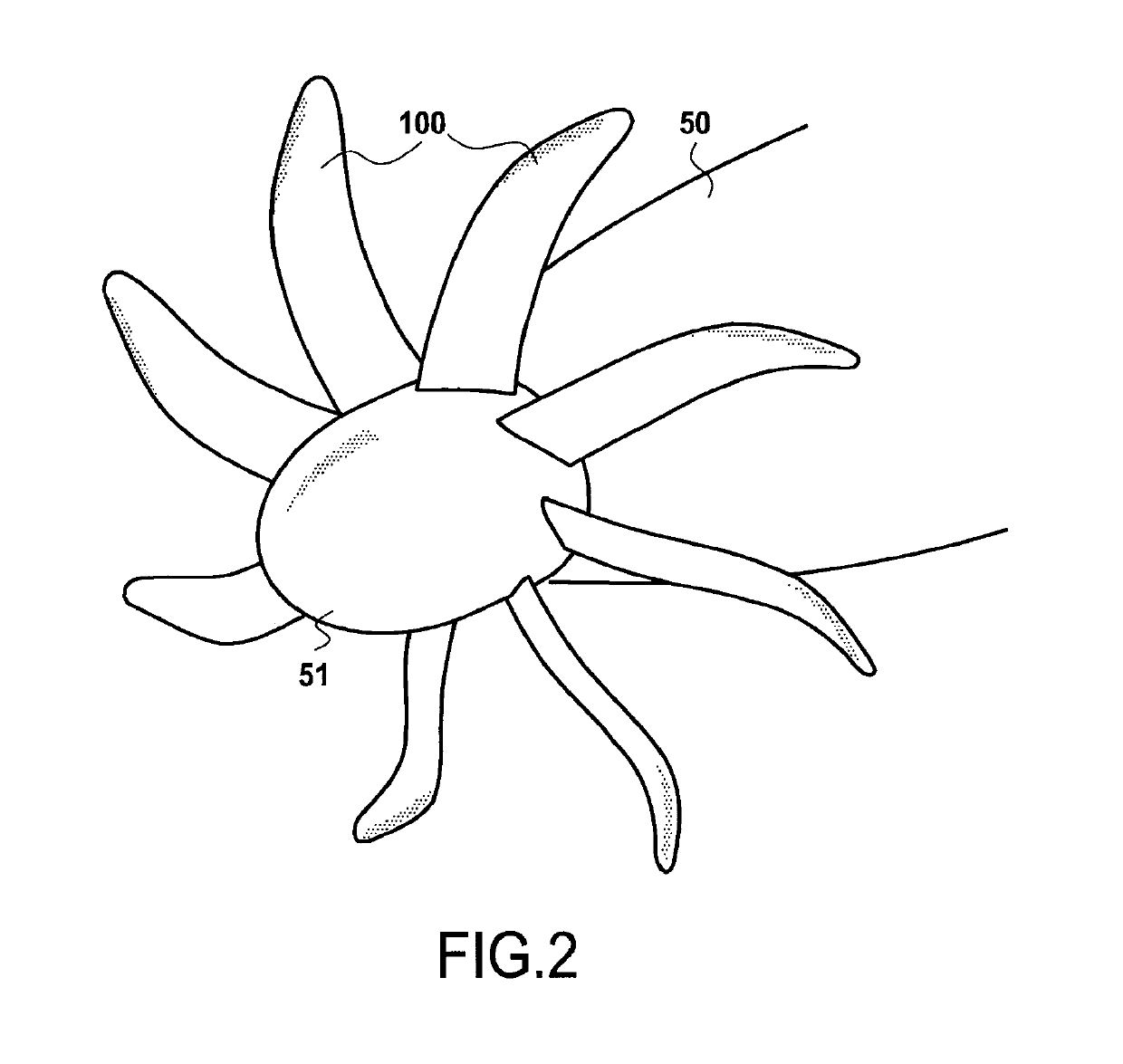
[0037]As shown in FIG. 2, the propeller 100 is mounted on a rotor 51 of a turboprop 50 by engaging the blade roots 120 in respective housings formed in the periphery of the rotor 51 (not shown i...


PUM

PropertyMeasurementUnit
dimensionsaaaaaaaaaa
heightaaaaaaaaaa
widthaaaaaaaaaa

Abstract

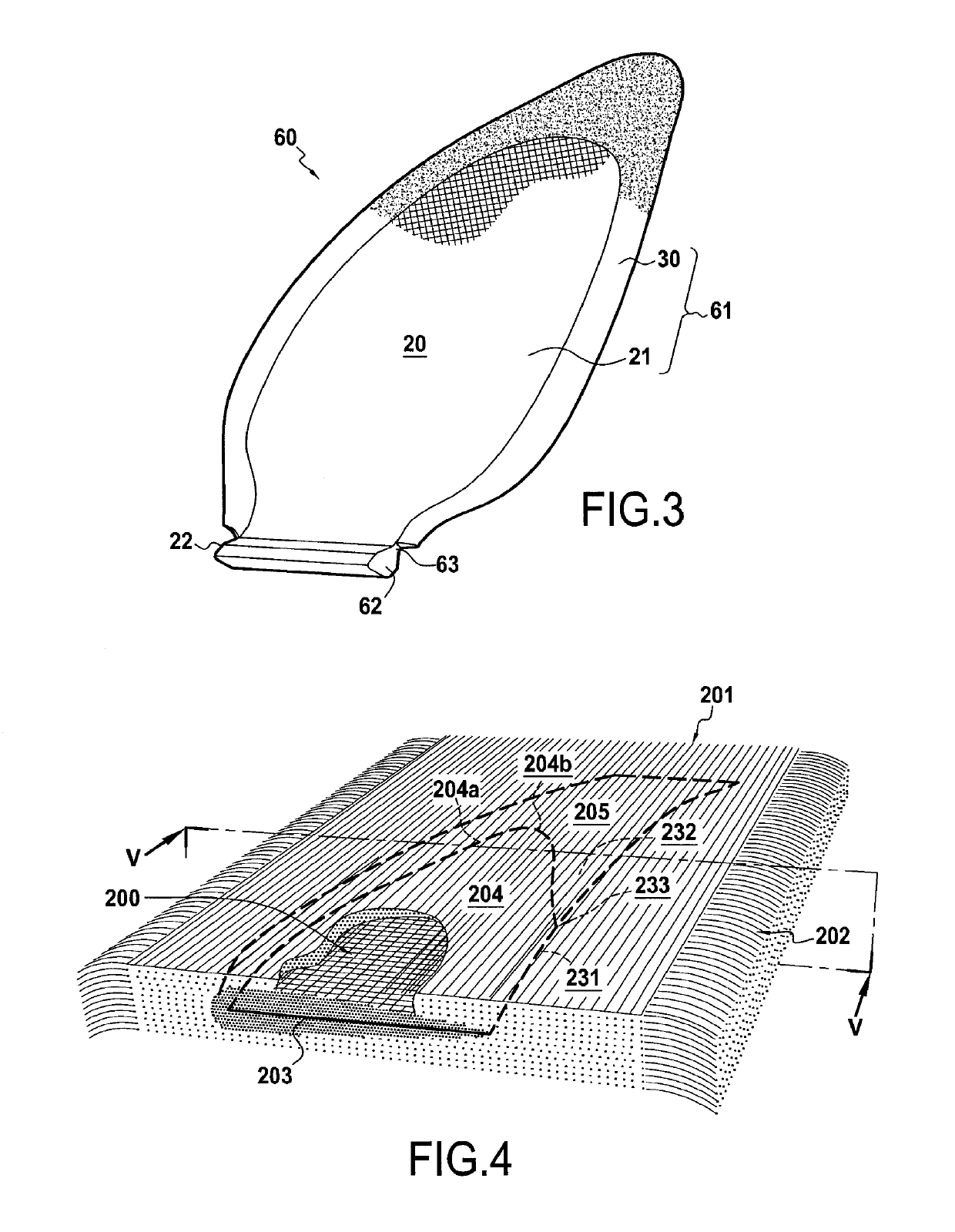
An aircraft propeller blade including a streamlined structure constituted by at least one piece of fiber reinforcement obtained by three-dimensionally weaving yarns and densified by a matrix, together with a spar including an enlarged portion extending outside the fiber reinforcement and forming the root of the blade, and a shaping portion present in a housing arranged inside the fiber reinforcement. The fiber reinforcement includes a non-interlinked zone forming the housing inside the fiber reinforcement. The non-interlinked zone opens out into the bottom portion and into the rear edge of the fiber reinforcement so as to form an opening for inserting the shaping portion of the spar into the housing of the fiber reinforcement. The opening present in the rear edge of the fiber reinforcement extends over a height that is less than the height of the housing.

Description

BACKGROUND OF THE INVENTION[0001]The present invention relates to the field of aircraft propeller blades, such as those present on turboprops.[0002]Propeller blades for turboprops are generally made of metal material. Although propeller blades made of metal material present good strength, they nevertheless present the drawback of being relatively heavy.[0003]In order to obtain lighter blades, it is known to use propeller blades that are made of composite material, i.e. by making structural parts out of fiber reinforcement and a resin matrix.[0004]Documents US 2013 / 0017093 and WO 2012 / 001279 describe making a propeller blade from a streamlined fiber structure into which a portion of a spar is inserted for the purpose of shaping the airfoil portion of the blade so as to form a propeller preform that is subsequently densified with a matrix. The fiber structure, which is made as a single piece by three-dimensional weaving, includes a non-interlinked zone serving to form a housing inside...

Claims


Application Information

Patent Timeline
Patent Type & Authority Patents(United States)
IPC IPC(8): B64C11/26B29C70/24D03D25/00B29D99/00F01D5/28B29C70/48B29K63/00B29K105/00B29K307/04B29L31/08
CPCB29D99/0025B64C11/26F01D5/282D03D25/005B29C70/48B29C70/24B29L2031/082B29K2715/00B29K2063/00Y02T50/43B29K2307/04B29K2105/253Y02T50/40B29B11/16
Inventor LAURENCEAU, ADRIENFABRE, ADRIEN JACQUES PHILIPPEGIMAT, MATTHIEU
Owner SN DETUDE & DE CONSTR DE MOTEURS DAVIATION S N E C M A
Learn More