Method for producing a dynamoelectric rotary machine, and dynamoelectric rotary machine

a technology of dynamoelectric rotary machine and dynamoelectric rotary machine, which is applied in the direction of magnetic circuit rotating parts, manufacturing stator/rotor body, and shape/form/construction of magnetic circuits, etc. it can solve the problems of time-consuming, resource-consuming, and sometimes error-prone processes of insulating materials such as mca tape or surface insulating materials, and achieve less error-prone and more time-saving effects

Active Publication Date: 2019-09-24
FLENDER GMBH
View PDF26 Cites 4 Cited by
  • Summary
  • Abstract
  • Description
  • Claims
  • Application Information

AI Technical Summary

Benefits of technology

[0008]Taking this as a starting point, the invention is based on the object of creating a method for insulating electrical conductors in slots which allows the insulation of windings, in particular the individual coils of a dynamoelectric machine in the slots, to be implemented in a manner that is less error-prone as well as comparatively more time-saving.
[0025]By way of example, the following high temperature-stable thermoplastics and / or elastomers are used for the spacers: PAEK, PI, PES, PPS, PPA, PAA, PFA and the individual family members of the polyether ketones (PEK), such as PEKK, PEEEK, PEEKK and PEKEKK. The fillers each contribute up to 70 percent by volume and inside the high temperature-stable thermoplastics and elastomers have milled glass fibers, mica powder or metal oxides. The milled glass fibers have lengths of 10 μm to a maximum of 5 mm and lead to mechanical reinforcement. Longer glass fibers do increase the viscosity but make processing by injection molding more difficult. The milled glass fibers used can be processed directly with the extruder, so production of inventive spacers is simplified.
[0029]The spacer can be profiled both toward the laminated core and / or coil. In addition to increased friction, profiling also has the advantage that the encapsulation can spread in the axial direction.

Problems solved by technology

Production of a main insulation of this kind comprising mica tape or surface insulating materials is a time- and therewith resource-consuming and sometimes also very error-prone process.

Method used


Image

  • Method for producing a dynamoelectric rotary machine, and dynamoelectric rotary machine
  • Method for producing a dynamoelectric rotary machine, and dynamoelectric rotary machine

Examples


Embodiment Construction

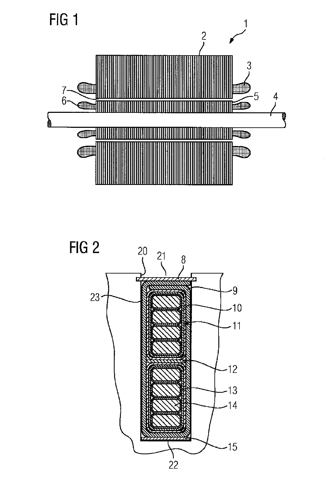
[0035]FIG. 1 shows the electrically active part of a dynamoelectric rotary machine 1 which has a stator 2, having an axially layered laminated core and a rotor 5 which is non-rotatably connected to a shaft 4, wherein the laminated core of the rotor 5 is also constructed with axial layers.

[0036]In this embodiment both the stator 2 and the rotor 5 each have a winding system 3, 6 which is arranged in axially running slots 20 (not visible in this view). The winding systems 3, 6 form winding heads at the end faces of stator 2 and rotor 5.

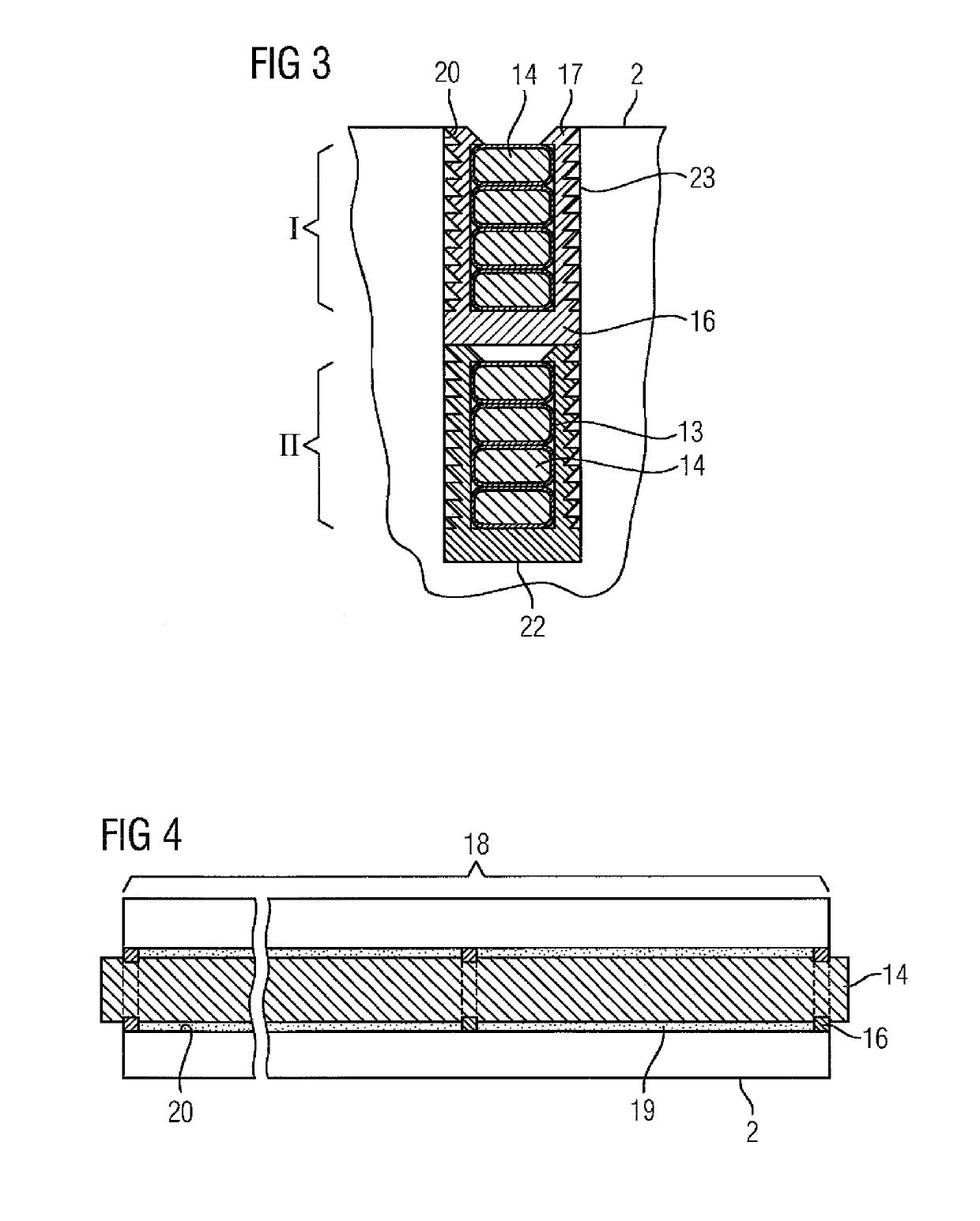
[0037]FIG. 2 shows a cross-section of a slot 20 which has a winding system 3 of a stator 2 which has a two-layer construction. A first layer with a conductor I is located directly at the slot opening 21 which points toward the air gap 7 of the dynamoelectric rotary machine 1. Present in the slot 20 are therefore two conductors I and II which each have a plurality of strands 14 which are arranged radially one above the other in this exemplary embodiment. ...


PUM


Abstract

The invention relates to a method for producing a rotor and / or a stator of a dynamoelectric rotary machine by means of the following steps: —producing pre-formed coils from an integral electrically conductive material or pre-insulated or coated electrically conductive wires, —fixing spacers to the pre-formed coil at predefinable intervals, —inserting the pre-formed coil, which is provided with spacers, into slots in a laminated core of a stator or rotor, —making contact with the individual pre-formed coils to form groups of coils and forming a winding system of a rotor and / or stator in accordance with a predefined circuit plan, —insulating the pre-formed coils or the winding system in the slots by complete encapsulation, in particular by complete vacuum encapsulation.

Description

CROSS-REFERENCES TO RELATED APPLICATIONS[0001]This application is the U.S. National Stage of International Application No. PCT / EP2014 / 064573, filed Jul. 8, 2014, which designated the United States and has been published as International Publication No. WO 2015 / 004119 and which claims the priority of European Patent Application, Serial No. 13176305.4, filed Jul. 12, 2013, pursuant to 35 U.S.C. 119(a)-(d).BACKGROUND OF THE INVENTION[0002]The invention relates to a method for producing a dynamoelectric rotary machine as well as to the dynamoelectric rotary machine itself.[0003]Dynamoelectric machines, in particular dynamoelectric rotary machines, have a laminated stator core and a laminated rotor core in which electrical conductors are preferably located in the stator in axially running slots. The conductors interact electromagnetically with permanent magnets of the rotor or a live winding of the rotor and therefore ensure drive or regenerative operation of the dynamoelectric machine.[...

Claims


Application Information

Patent Timeline
Patent Type & Authority Patents(United States)
IPC IPC(8): H02K3/48H02K3/34H02K15/12H02K1/12H02K1/22H02K3/38H02K15/02H02K15/00
CPCH02K15/12H02K3/345H02K3/38H02K1/22H02K3/48H02K1/12H02K15/02H02K15/0018
Inventor GRÜBEL, ANDRÉKLAUSSNER, BERNHARDSCHIRM, DIETERÜBLER, MATTHIAS
Owner FLENDER GMBH
Why Eureka
Try Eureka