Beaconing in small wavelength wireless networks

a wireless network and small wavelength technology, applied in the field of directional wireless communications, can solve the problems of high data demand, high loss of free-space paths, high penetration, etc., and achieve the effect of improving the mechanism of beaconing

Active Publication Date: 2019-10-01
SONY CORP +1
View PDF7 Cites 0 Cited by
  • Summary
  • Abstract
  • Description
  • Claims
  • Application Information

AI Technical Summary

Benefits of technology

[0012]It is important to be able to setup and maintain mmWave communications in a mesh topology network without causing significant signaling overhead or network discovery delay. In the disclosed technology two different types of beacon signals are utilized: (1) a communication beacon (peer beacon) and (2) a discovery beacon. The use of these two beacons allows separation of discovery function and network maintenance function, so a node station (STA) embeds less information in each of these strategically targeted beacons. Using the present apparatus and method with these separated beacons reduces signaling overhead.
[0013]The disclosed technology coordinates discovery beacon transmissions among STAs in a network, toward reducing unnecessary beacon transmissions for the purpose of network discovery. The disclosed apparatus and method defines a set of rules how the coordination should be performed in an efficient manner. For example, the disclosed technology reduces the number of sectors for communication (peer) beacon transmission, to reduce the number of beacon frames to be transmitted. The disclosed technology also defines a set of rules which allow both passive scanning and active scanning with reduced beaconing overhead. Based on these rules, new stations (those seeking to join the mesh network) can discover an existing network with limited network delay.
[0017]Beamforming (BF): a directional transmission that does not use an omnidirectional antenna pattern or quasi-Omni antenna pattern. Beamforming is used at a transmitter to improve received signal power or signal-to-noise ratio (SNR) at an intended receiver.

Problems solved by technology

Use of current sub-6 GHz wireless technology is not sufficient to cope with high data demands.
High free-space path loss, high penetration, reflection and diffraction losses reduce the available diversity and limit non-line-of-sight (NLOS) communications.
This task is further challenging in mmWave communications due to directional transmissions.
In addition, those technologies which utilize directional wireless network communications often have very high overhead demands in regards to the generation of beacon signals.

Method used


Image

  • Beaconing in small wavelength wireless networks
  • Beaconing in small wavelength wireless networks
  • Beaconing in small wavelength wireless networks

Examples


embodiment 150

[0158]FIG. 17 illustrates an embodiment 150 of a node 152 transmitting in directions 154a through 154n, during sweeping 156 of a mesh network discovery frame in a quasi-Omni directional transmission.

[0159]4.4. Efficient BF Training through Peer and Discovery Beacons

[0160]4.4.1. Peer Beacon Updates

[0161]In directional communications, e.g. 60 GHz WLAN, beacon transmissions may be utilized in at least one embodiment of the present disclosure as part of the BF training required to establish robust communications between peers. The discovery beacons described herein can initiate the BF training, such as for example using SLS phase.

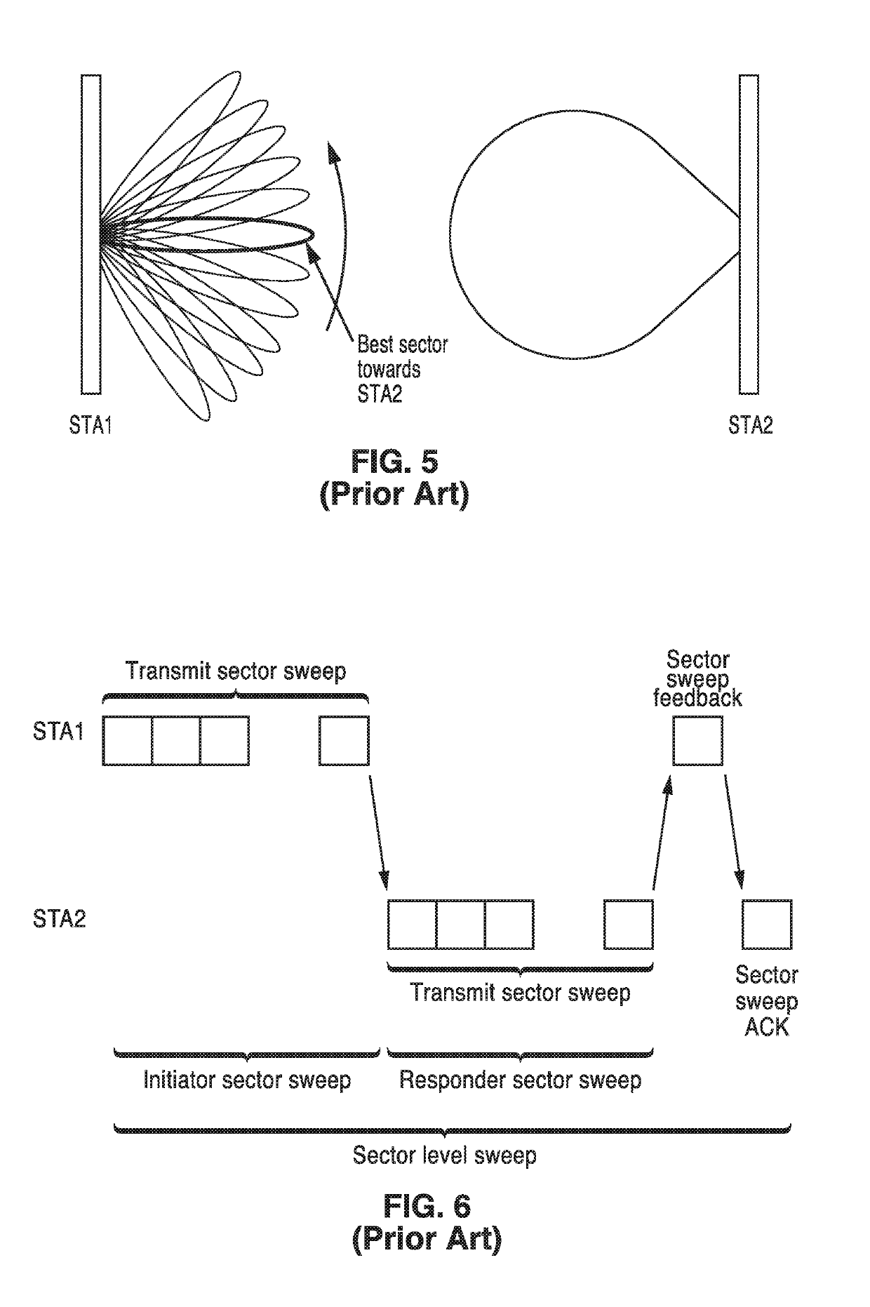
[0162]A mesh node records the best sector information from the BF training that happens during and shortly after transmitting the discovery beacons. For peer beacons, the mesh node transmits beacons only in sectors corresponding to best sectors towards peer mesh nodes.

[0163]FIG. 18A and FIG. 18B illustrate an example embodiment of providing additional robustnes...

embodiment 230

[0166]FIG. 20 illustrates an embodiment 230 of training database creation and updates. After a few beacon intervals (BIs), the BF training may need to be updated. The discovery beacons provide either the refresh cycle of the BF training or a BF training with a new peer node.

[0167]The process commences 232 with discovery beacons being received 234 from STA n, followed by retrieval 236 of an entry of STA n in a record of best sectors from record of best sectors 238. A check 240 is made to determine if STA n has an entry in the record of best sectors. If there is no such entry, then an entry is made 242 into the record of best sectors 238. Otherwise, if there is an existing entry, then the existing and current data are compared 244 and BF training information is updated 246 for STA n prior to the processing ending 248.

[0168]4.5. Steady State BM Handling Protocol

[0169]4.5.1. Master Beacon Switching

[0170]The network in steady state moves (rotates) the beacon masters among the network nod...

embodiment 910

[0257]In FIG. 37 embodiment 910, a number of network entities are depicted as new node 912 seeking to join the network, neighbor 1 node 914, neighbor 2 node 916, neighbor 3 node 918, beacon master 920, central entity 922 and mesh node 924. Beacon master 920 sends 926 discovery beacons in all directions, 928, 930 and 932, with these beacons reaching the new node in this case. The new node 912 responds with beacon response 934 to the beacon master 920 which announces 936 the new node to the central entity 922. The central entity then announces 938 the beacon master schedule to all nodes 940, 942, 944, 946, 948, except the new node 912. When helpful, the neighbor that discovered the new node sends the new node a frame to tell that node about the new schedule and some information that aids beamforming with other neighbor. Neighbor 3 node 918 generates 950 discovery beacons in all directions 952, 954, 956. New node 912 responds with a beacon response 958 to neighbor 3 node 918. Neighbor ...


PUM


Abstract

Reduced signaling overhead is provided in an apparatus and method for communications within a mesh network. The communications involve using two different beacon signals. A peer beacon contains time synchronization and resource management information to maintain existing links among one or more neighboring peer stations, while a separate network discovery beacon contains mesh network profile information that identifies the mesh network to aid network discovery for wireless communication stations wanting to join the mesh network. Embodiments describe coordination between peer stations to determine which stations are to send the network discovery beacons, so that at any given period of time not all stations need to be transmitting the discovery beacons.

Description

CROSS-REFERENCE TO RELATED APPLICATIONS[0001]This application claims priority to, and the benefit of, U.S. provisional patent application Ser. No. 62 / 550,028 filed on Aug. 25, 2017, incorporated herein by reference in its entirety.STATEMENT REGARDING FEDERALLY SPONSORED RESEARCH OR DEVELOPMENT[0002]Not ApplicableINCORPORATION-BY-REFERENCE OF COMPUTER PROGRAM APPENDIX[0003]Not ApplicableNOTICE OF MATERIAL SUBJECT TO COPYRIGHT PROTECTION[0004]A portion of the material in this patent document may be subject to copyright protection under the copyright laws of the United States and of other countries. The owner of the copyright rights has no objection to the facsimile reproduction by anyone of the patent document or the patent disclosure, as it appears in the United States Patent and Trademark Office publicly available file or records, but otherwise reserves all copyright rights whatsoever. The copyright owner does not hereby waive any of its rights to have this patent document maintaine...

Claims


Application Information

Patent Timeline
Patent Type & Authority Patents(United States)
IPC IPC(8): H04W40/24H04W16/28H04W8/00H04L12/24H04W84/12H04W48/16H04W84/18H04B7/06
CPCH04W40/244H04W8/005H04W16/28H04W48/16H04B7/0695H04L41/12H04W84/12H04W84/18H04W40/246H04W40/06
Inventor ABOUELSEOUD, MOHAMEDABDALLAH, RAMYSAKODA, KAZUYUKI
Owner SONY CORP
Why Eureka
Try Eureka