System and method for minimizing transport related performance losses in a flow battery system

a flow battery and performance loss technology, applied in the field of rechargeable batteries, can solve the problems of only operating successfully flow batteries and flow battery systems, diffusive transport cannot be relied upon as a transport mechanism, and the concentration of active materials tends toward relatively small values, so as to achieve the effect of minimizing performance losses in the system

Active Publication Date: 2019-10-08
ROBERT BOSCH GMBH
View PDF11 Cites 0 Cited by
  • Summary
  • Abstract
  • Description
  • Claims
  • Application Information

AI Technical Summary

Benefits of technology

[0015]In one embodiment, a flow battery system minimizes performance losses in the system. The flow battery system includes at least one cell, a first tank including a liquid electrolyte, a pump operably connected to the first tank and to the at least one cell, and a second electrolyte tank operably connected to the at least one cell. The system further includes a memory including program instructions stored therein, at least one sensor configured to a generate at least one signal associated with a sensed condition of the battery system, and a controller operably connected to the at least one sensor, the pump, and the memory. The controller is configured to determine a dead zone condition exists based upon the at least one signal and control the pump to pulse flow of the liquid electrolyte to the at least one cell based upon the determination. The controller is therefore advantageously able to adjust the flow based on the conditions in the battery to prevent and remedy dead zones or other detrimental conditions.
[0023]In another embodiment according to the disclosure, a method of operating a flow battery system minimizes flow losses in the battery system. The method includes generating, with at least one sensor, at least one signal associated with a sensed condition of a battery system having at least one cell, a first tank including a liquid electrolyte, and a second electrolyte tank operably connected to the at least one cell. The method further comprises determining, with a controller configured to execute programmed instructions stored in a memory, a dead zone condition exists in the battery system based upon the at least one signal, and executing programmed instructions stored in the memory with the controller to control a pump operably connected to the first tank and to the at least one cell to pulse flow of the liquid electrolyte to the at least one cell based upon the determination.

Problems solved by technology

While the H2 / Br2 system has a high power density, numerous challenges remain, including ensuring safe operation of the battery and achieving a low-cost design for a H2 / Br2 battery system.
However, when the battery is either fully charged or fully discharged, the concentration of the active materials tends toward relatively small values.
However, when high current densities are needed, diffusive transport cannot be relied upon as a transport mechanism because it is a relatively slow process, and migration is also limited by the intrinsic mobility of species within a solution.
Flow batteries and flow battery systems are only operated successfully if sufficient concentrations of reactant materials are transported to electrochemical reaction zones on both sides of the battery's cell membranes.
During operation of the battery, it is possible that transport of active material through regions of the electrode slows, and the active material that has been electrochemically depleted in these regions may not be replenished with fresh active material from the system storage tanks.
The regions in which the electrochemically depleted material is not replenished experience low active material concentrations, and are referred to herein as “dead zones.” Low active material concentrations in some regions can result in reduced performance of the battery, for example causing a decrease in the overall cell voltage during discharge, an increase in the cell voltage during charge, or local changes in the porous electrode's potential field.
Changes in the cell voltage negatively impact the efficiency of the battery cell's energy storage capabilities.
Furthermore, local changes in the electrode potential can cause cell corrosion and degradation.

Method used


Image

  • System and method for minimizing transport related performance losses in a flow battery system
  • System and method for minimizing transport related performance losses in a flow battery system
  • System and method for minimizing transport related performance losses in a flow battery system

Examples


Embodiment Construction

[0045]For the purposes of promoting an understanding of the principles of the embodiments disclosed herein, reference is now made to the drawings and descriptions in the following written specification. No limitation to the scope of the subject matter is intended by the references. The present disclosure also includes any alterations and modifications to the illustrated embodiments and includes further applications of the principles of the disclosed embodiments as would normally occur to one skilled in the art to which this disclosure pertains.

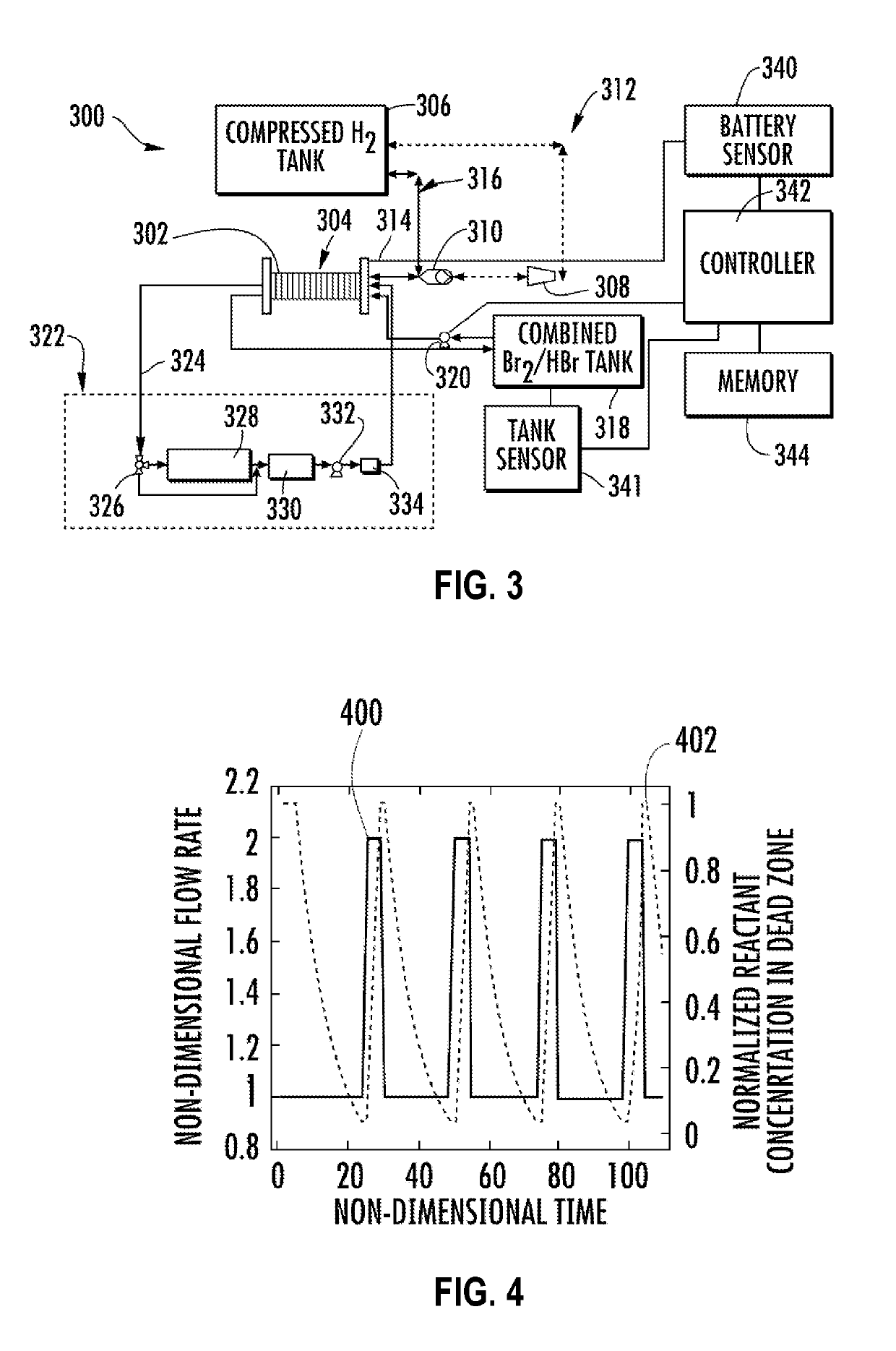
[0046]FIG. 3 schematically illustrates an embodiment an H2 / Br2 flow battery system 300 according to the present disclosure. A plurality of cells 302 are stacked together to form a battery stack 304. A supply tank 306 for the hydrogen gas H2 is coupled to a compressor 308, which is coupled to a pressure regulator 310. A mechanical compression line 312, in one embodiment, extends from the tank 306 through the compressor 308, through the pressure...


PUM

PropertyMeasurementUnit
areaaaaaaaaaaa
energy densityaaaaaaaaaa
reaction timeaaaaaaaaaa

Abstract

A flow battery system and method of operating the system minimizes performance losses. The flow battery system includes at least one cell, a first tank including a liquid electrolyte, a pump operably connected to the first tank and to the at least one cell, and a second electrolyte tank operably connected to the at least one cell. The flow battery system further includes a memory including program instructions stored therein, at least one sensor configured to a generate at least one signal associated with a sensed condition of the battery system, and a controller operably connected to the at least one sensor, the pump, and the memory and configured to execute the program instructions to determine a dead zone condition exists based upon the at least one signal, and control the pump to pulse flow of the liquid electrolyte to the at least one cell based upon the determination.

Description

CLAIM OF PRIORITY[0001]This application is a 35 U.S.C. § 371 National Stage Application of PCT / US2014 / 066866, filed on Nov. 21, 2014, which claims the benefit of priority to U.S. Provisional Application No. 61 / 906,999, filed on Nov. 21, 2013 and entitled “System and Method for Minimizing Transport Related Performance Losses in a Flow Battery System,” the disclosures of which are incorporated herein by reference in their entireties.STATEMENT REGARDING FEDERALLY SPONSORED RESEARCH OR DEVELOPMENT[0002]This invention was made with government support under DE-AR0000137 awarded by the Department of Energy Advanced Research Projects Agency-Energy. The government has certain rights in the invention.TECHNICAL FIELD[0003]This disclosure relates generally to the field of rechargeable batteries and more particularly to flow batteries and flow battery systems.BACKGROUND[0004]As intermittent renewable energy sources such as wind and solar increase their share of overall energy production, a metho...

Claims


Application Information

Patent Timeline
Patent Type & Authority Patents(United States)
IPC IPC(8): H01M8/04276H01M8/20H01M8/18H01M8/04746H01M8/04537H01M8/0444H01M8/04223
CPCH01M8/04559H01M8/04276H01M8/04753H01M8/188H01M8/0444H01M8/20H01M8/04455H01M8/04552Y02E60/528H01M8/04231Y02E60/50
Inventor KNUDSEN, EDWARDALBERTUS, PAUL
Owner ROBERT BOSCH GMBH
Why Eureka
Try Eureka