Voltage droop reduction in a processor

a technology of voltage droop reduction and processor, which is applied in the direction of data processing power supply, program control, instruments, etc., can solve the problems of sudden increase in noise, affecting the performance of the processor, and causing a droop in the supply voltage, so as to reduce the voltage droop, reduce the noise of the power grid, and minimize performance loss

Inactive Publication Date: 2016-04-07
IBM CORP
View PDF3 Cites 13 Cited by
  • Summary
  • Abstract
  • Description
  • Claims
  • Application Information

AI Technical Summary

Benefits of technology

[0007]In view of the foregoing, there may be a need for an improved processor and method for reducing power grid noise to reduce any voltage droop, while minimizing performance loss, in a processor system with multiple processor cores sharing a common supply rail.

Problems solved by technology

In a processor there is noise generated by circuit switching activity at each clock cycle by nodes, busses, and other circuit components sharing a common supply rail.
One result of noise generated by circuit switching activity, also referred to as power grid noise or di / dt noise, is that a sudden increase in noise will induce a droop in the supply voltage to the common supply rail of the power distribution network.
A sudden, large droop in the supply voltage slows down the circuit response and therefore could cause timing errors on the logical circuit.
Since many cores can be activated simultaneously, one limitation of implementing decoupling capacitors to reduce noise is in the case where there is a sudden burst of activity on one or more processor cores, increasing the current, and because ΔI is directly proportional to the number of cores on the common supply rail, the sudden increase in ΔI outweighs the noise reduction by the charge reservoirs of the decoupling capacitors, triggering a voltage droop.
The known method may not detect all logical operation activities which may lead to a voltage droop.

Method used


Image

  • Voltage droop reduction in a processor
  • Voltage droop reduction in a processor
  • Voltage droop reduction in a processor

Examples


Embodiment Construction

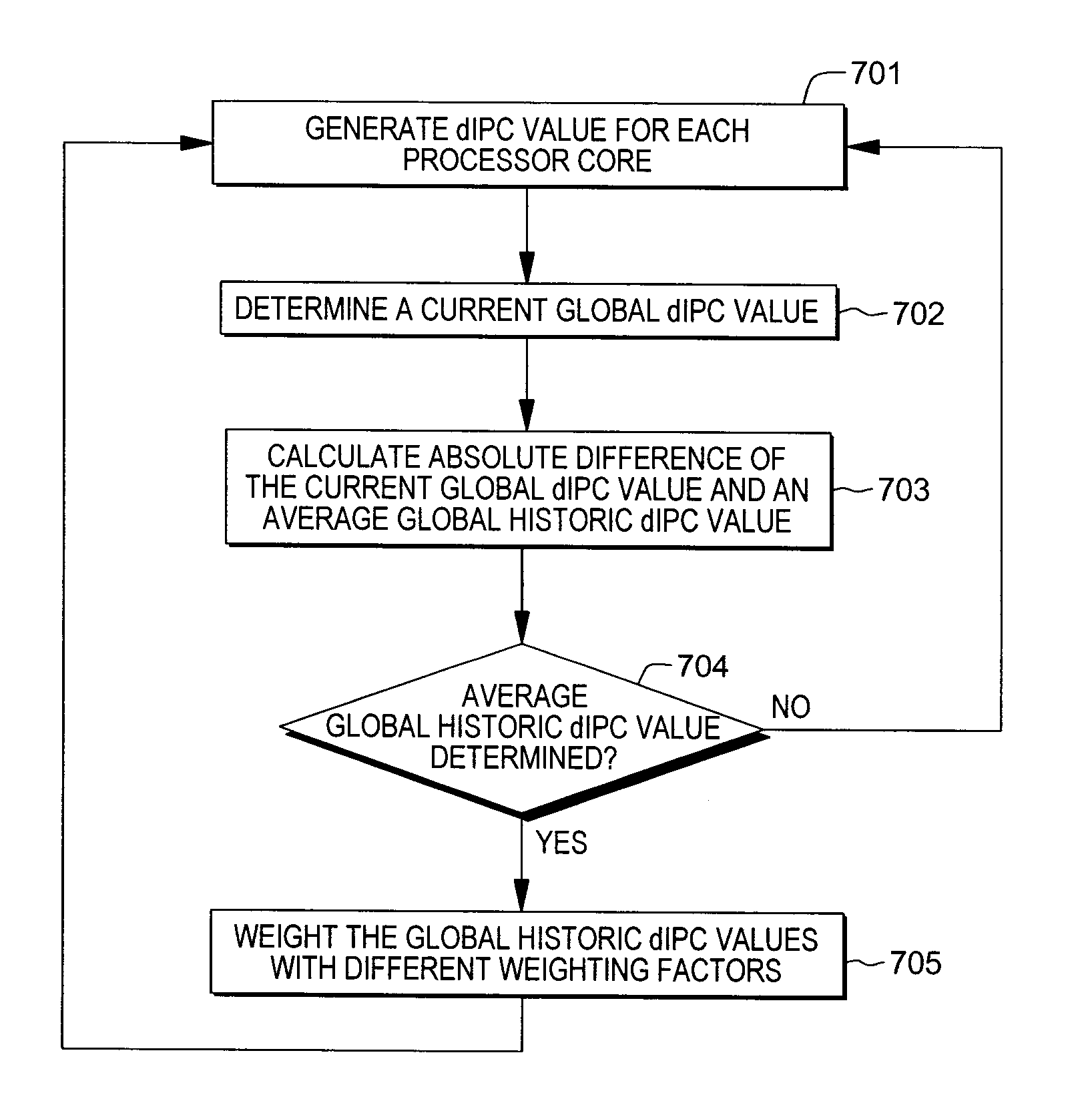
[0018]As explained further below, in one or more aspects, instructions per cycle (IPC) are being dynamically changed herein. Thus, the term dynamic instructions per cycle (dIPC) is used throughout this description.

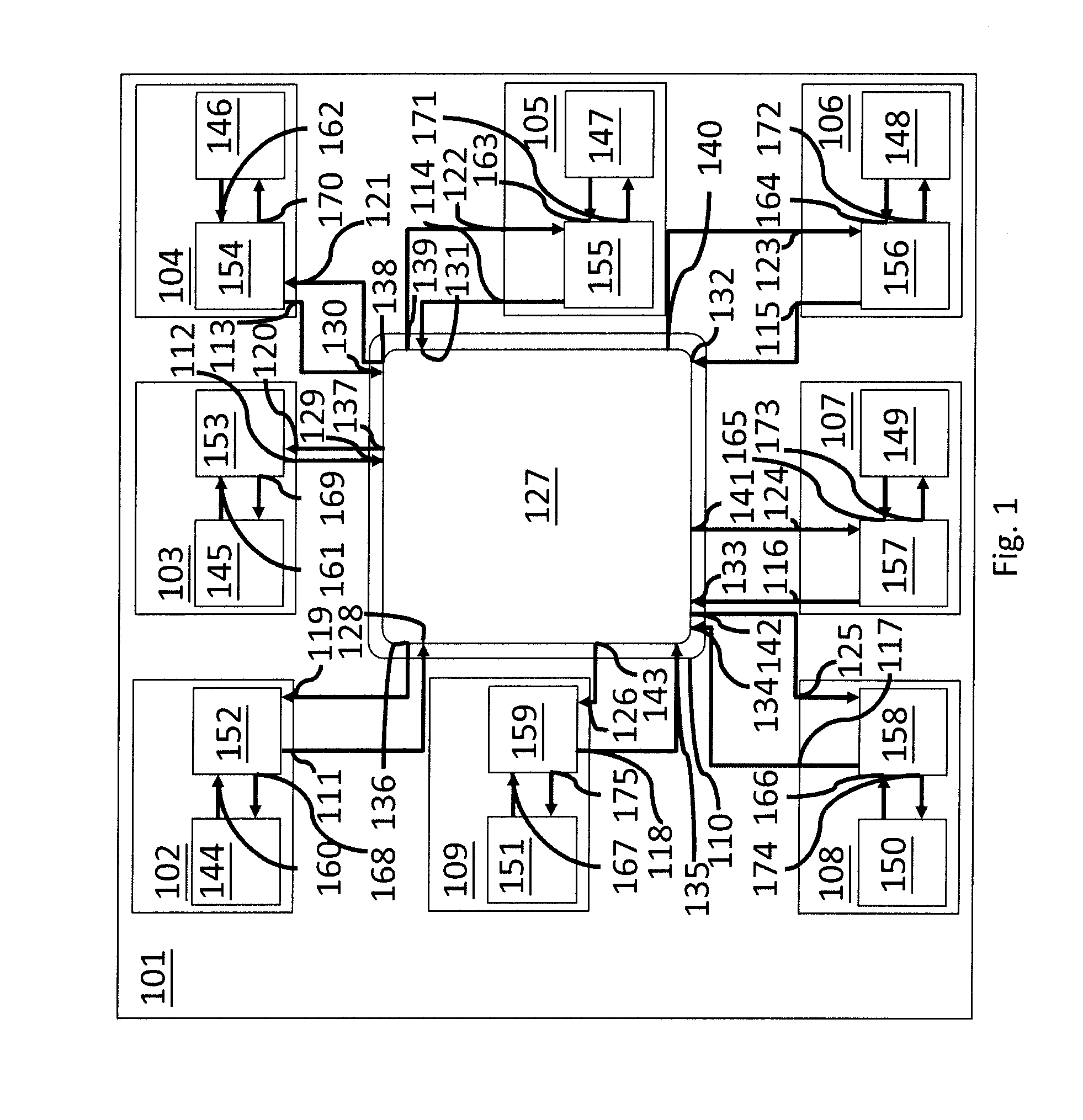
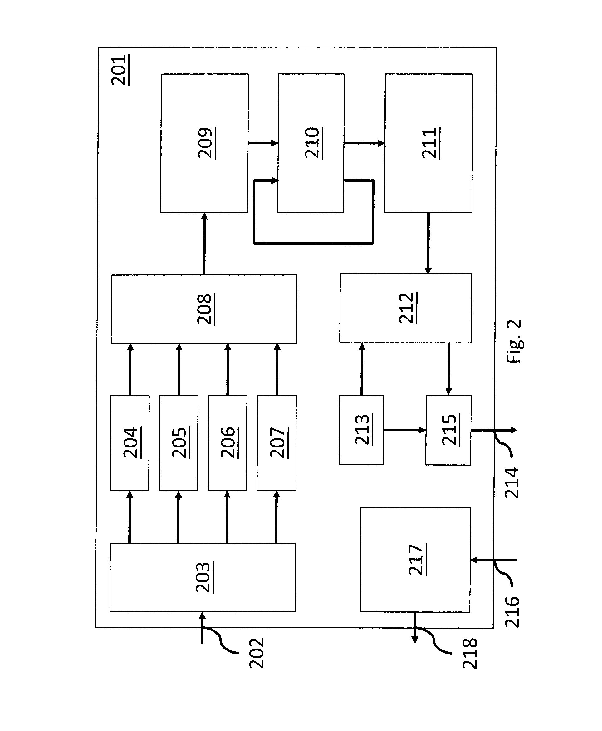
[0019]For one or more aspects of the present invention, the invention may be implemented in a processor comprising a common supply rail, one or more processor cores, wherein the one or more processor cores share the common supply rail, and wherein each of the one or more processor cores comprises an output for outputting a core dIPC value and an input for inputting a core throttling signal, and a chip power management logic, in particular separate from the one or more processor cores, wherein the chip power management logic comprises at least one input for inputting the core dIPC value, a threshold register for registering a dIPC threshold value, a chip dIPC register for registering a current global dIPC value derived from the at least one core dIPC value, at least one chi...


PUM


Abstract

A processor is provided having a common supply rail, and one or more processor cores, where the one or more processor cores share the common supply rail. Each processor core(s) includes a core dIPC value output and a core throttling signal input, and a chip power management logic, which has at least one input for inputting the core dIPC value, a threshold register for a dIPC threshold value, a chip dIPC register for a current global dIPC value, at least one chip dIPC history register for a historic global dIPC value, a subtractor providing an absolute difference of an average historic global dIPC derived from the historic global dIPC value and the current global dIPC value, a magnitude comparator providing a throttling signal when the absolute difference is above the dIPC threshold value, and at least one output for outputting a core throttling signal to the processor core(s).

Description

PRIOR FOREIGN APPLICATION[0001]This application claims priority from United Kingdom (GB) patent application number 1417446.0, filed Oct. 2, 2014, which is hereby incorporated herein by reference in its entirety.BACKGROUND[0002]The embodiment of the invention relates generally to reducing power grid noise in a processor and particularly to reducing power grid noise in a processor while minimizing performance loss.[0003]In high performance processors, or other integrated circuits (ICs), to increase the processing performance of the processor, the processor chip design typically includes one or more of one or more processor cores and one or more pipelines connecting the processor cores. In addition, in a high performance system, processor system designs often include multiple chips sharing a common supply rail of a power distribution network providing a supply voltage. As the number of processor cores on a same chip or across multiple chips, all sharing a common supply rail, increases,...

Claims


Application Information

Patent Timeline
Patent Type & Authority Applications(United States)
IPC IPC(8): G06F1/26
CPCG06F1/26G06F1/28G06F1/3206G06F9/5094
Inventor CURRAN, BRIAN W.LOBO, PREETHAM M.RIZZOLO, RICHARD F.WARNOCK, JAMES D.WEBEL, TOBIAS
Owner IBM CORP
Why Eureka
Try Eureka