Piezoelectric ceramic, piezoelectric element comprising it, and piezoelectric device comprising piezoelectric element

a piezoelectric element and piezoelectric technology, applied in piezoelectric/electrostrictive/magnetostrictive devices, basic electric elements, electrical apparatuses, etc., can solve the problem of a sudden reduction of displacement, the difficulty of achieving both high oscillation speed and low heat release in the prior, and the increase of the displacement. , the effect of low vibration-induced heat release and sufficient oscillation speed

Inactive Publication Date: 2013-10-22
TDK CORPARATION
View PDF7 Cites 0 Cited by
  • Summary
  • Abstract
  • Description
  • Claims
  • Application Information

AI Technical Summary

Benefits of technology

[0006]Piezoelectric ceramics are preferably capable of operation at high oscillation speeds as mentioned above, but also preferably have minimal vibration-induced heat release, from the viewpoint of effects on surrounding elements during device usage and of minimizing loss of performance due to thermal runaway of the device itself. Generally, however, increasing oscillation speed tends to result in greater heat release due to loss of internal energy, and therefore it has been quite difficult to achieve both high oscillation speed and low heat release in the prior art.
[0007]It is therefore desirable, in piezoelectric ceramics, to reduce energy loss to a minimum during conversion of electrical energy to mechanical vibrational energy, thus reducing heat release to prevent thermal runaway.

Problems solved by technology

Generally, however, increasing oscillation speed tends to result in greater heat release due to loss of internal energy, and therefore it has been quite difficult to achieve both high oscillation speed and low heat release in the prior art.
When such conventional piezoelectric ceramics are used as resonators, increased deviation between resonance frequency and driving frequency has resulted in the problem of a sudden reduction of displacement.

Method used


Image

  • Piezoelectric ceramic, piezoelectric element comprising it, and piezoelectric device comprising piezoelectric element
  • Piezoelectric ceramic, piezoelectric element comprising it, and piezoelectric device comprising piezoelectric element
  • Piezoelectric ceramic, piezoelectric element comprising it, and piezoelectric device comprising piezoelectric element

Examples


examples

[0091]The present invention will now be explained in greater detail based on examples and comparative examples, with the understanding that these examples are in no way limitative on the invention.

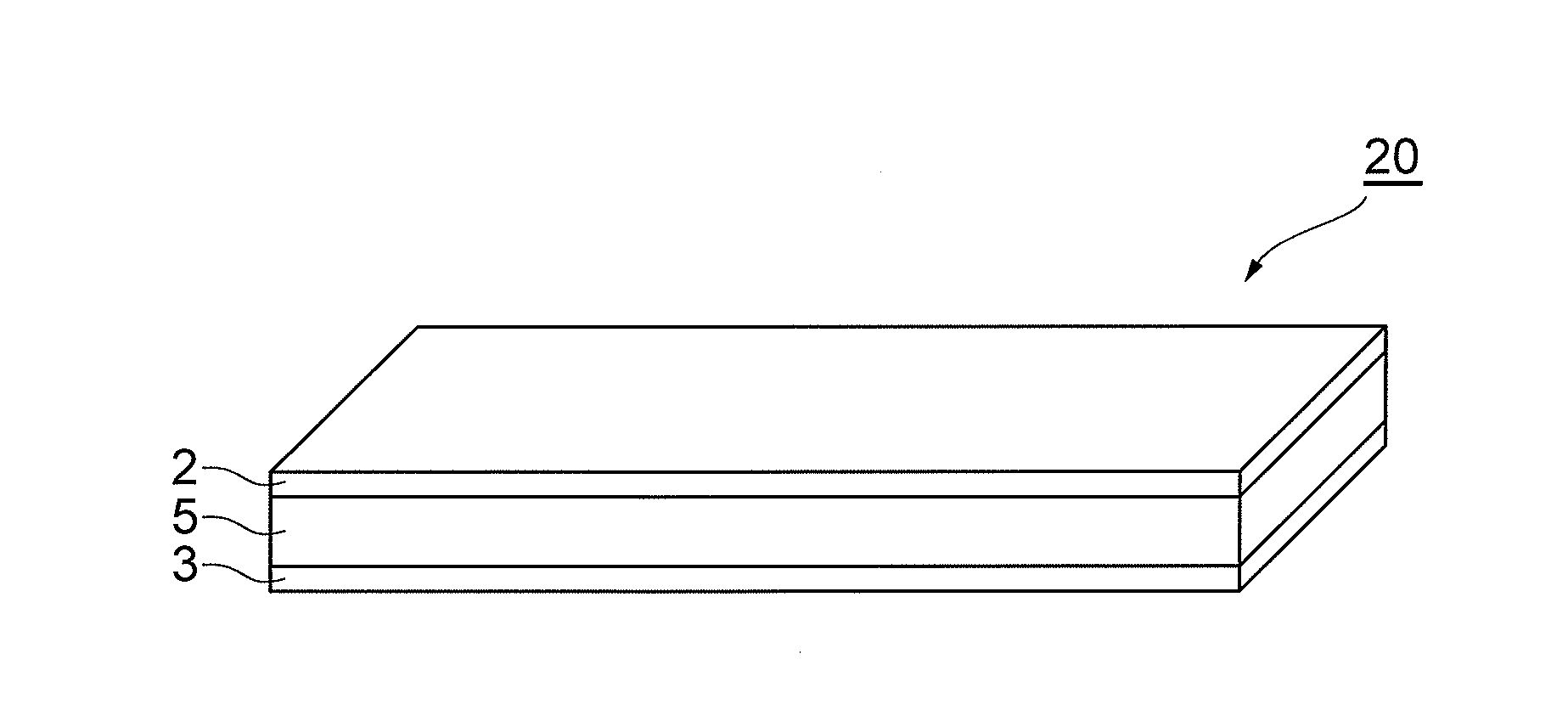
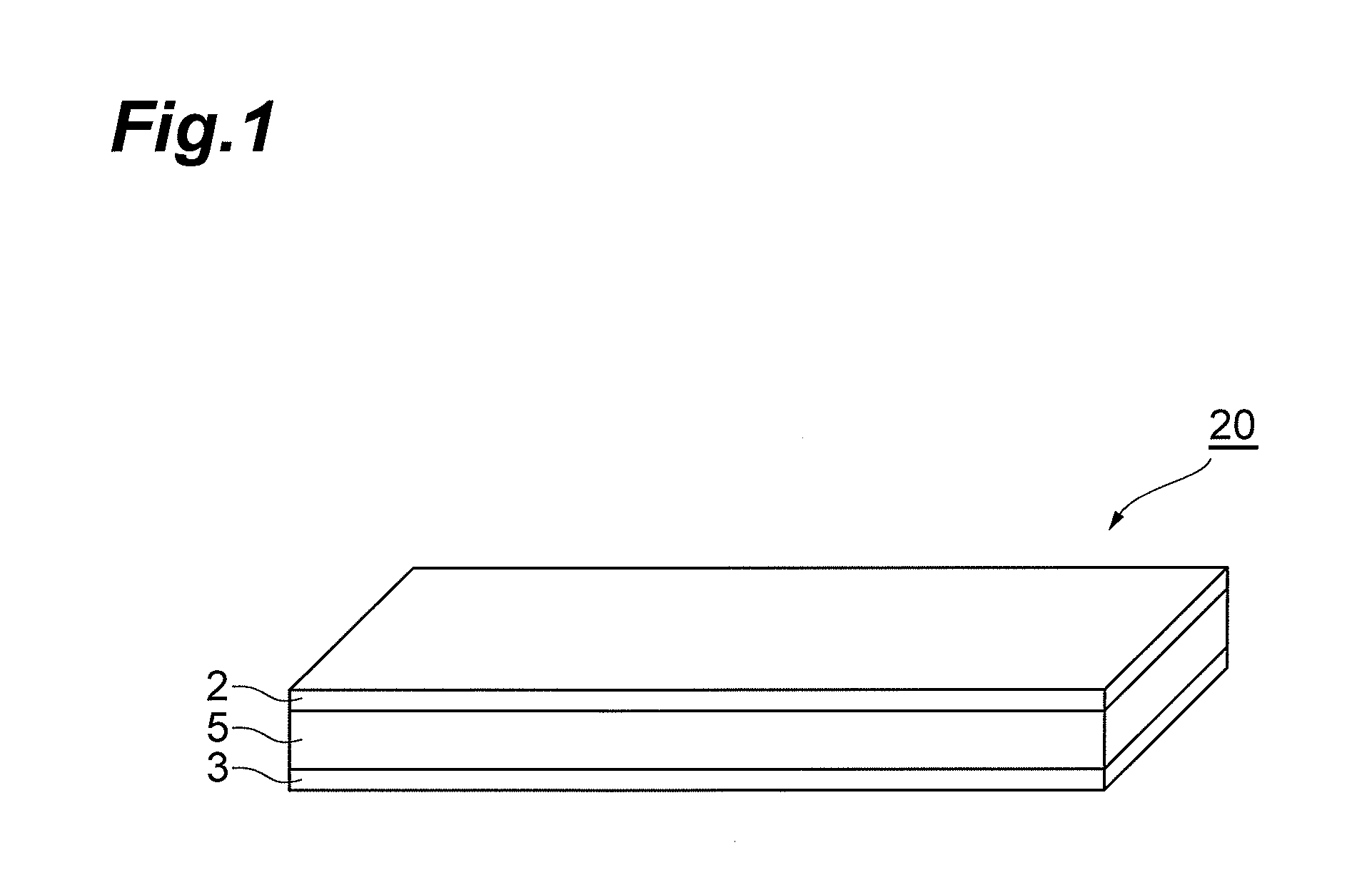
First Piezoelectric Element

[Production of Oscillators (Piezoelectric Elements): Samples No. 1-1 to 1-26 and 1-31 to 1-42]

[0092]First, lead oxide (PbO), titanium oxide (TiO2), zirconium oxide (ZrO2), zinc oxide (ZnO), niobium oxide (Nb2O5), tin oxide (SnO2), calcium carbonate (CaCO3), strontium carbonate (SrCO3), barium carbonate (BaCO3), manganese carbonate (MnCO3) and ytterbium oxide (Yb2O3) were prepared as starting materials for the piezoelectric ceramic, and the powders were combined in different proportions so that each of the post-firing compositions was (Pb1-aA1a)TixZr1-x-y-z-b(Zn1 / 3Nb2 / 3)y(Yb1 / 2Nb1 / 2)zSnbO3+c mass % MnCO3, with the type of element A and the numerical values of a, b, c, x, y and z as shown in Table 1, to prepare different mixtures.

[0093]Each mixture was subjected to...

examples 2-1 to 2-35

, Comparative Examples 2-1 to 2-8

[0111]As the starting materials for fabrication of piezoelectric ceramics, there were prepared powders of lead oxide (PbO), titanium oxide (TiO2), zirconium oxide (ZrO2), zinc oxide (ZnO), niobium oxide (Nb2O5), tin oxide (SnO2), calcium carbonate (CaCO3), strontium carbonate (SrCO3), barium carbonate (BaCO3) and manganese carbonate (MnCO3).

[0112]The starting powders were weighed out so that the fired piezoelectric ceramics (sintered materials) satisfied the compositions listed in Tables 3 and 4. In Tables 3 and 4, a, b, x and y represent the numerical values of a, b, x and y in formula (2), respectively, and A1 and A2 represent elements A1 and A2 in formula (2). Also, c represents the manganese content, in terms of MnCO3, with respect to the complex oxide represented by formula (2). Also, aSr, aCa and aBa represent the respective ratios of Sr, Ca and Ba when 2 or more elements were used as A1, and yZnNb and yZnW represent the respective ratios of Zn...


PUM

PropertyMeasurementUnit
heightaaaaaaaaaa
widthaaaaaaaaaa
lengthaaaaaaaaaa

Abstract

According to a preferred embodiment, the piezoelectric ceramic includes a complex oxide having the composition represented by formula (1) or (2), and Mn at 0.2-1.2 mass % or 0.2-3 mass %, respectively, in terms of MnCO3.(Pb1-aA1a)TixZr1-x-y-z-b(Zn1 / 3A22 / 3)y(Yb1 / 2A21 / 2)zSnbO3  (1)(Pb1-aA1a)TixZr1-x-y-b(Zn1 / 3A22 / 3)ySnbO3  (2)[In formula (1), A1 represents at least one element selected from the group consisting of Ca, Sr and Ba, and A2 is at least one element selected from the group consisting of Nb, Ta and Sb, and includes at least Nb. In formula (2), A1 represents at least one element selected from among Ca, Sr and Ba, A2 represents at least one element selected from among Nb and W, and A2 includes at least Nb.]

Description

BACKGROUND OF THE INVENTION[0001]1. Field of the Invention[0002]The present invention relates to a piezoelectric ceramic, to a piezoelectric element comprising it, and to a piezoelectric device comprising the piezoelectric element.[0003]2. Related Background Art[0004]Ultrasonic motors and piezoelectric transducers are examples of applications of piezoelectric ceramics in high-power devices. Such devices require materials that operate at high oscillation speeds and exhibit large amplitudes.[0005]Examples of piezoelectric ceramics that can be driven at high oscillation speeds include piezoelectric ceramics comprising a main component which is a system of lead zirconate titanate (Pb(Zr, Ti)3, (PZT)), as a perovskite-type compound, and an accessory component, known as a relaxer. It is known that particularly high oscillation speeds can be obtained with lead zirconate titanate / lead zinc niobate (Pb(Zr, Ti)O3—Pb(Zn, Nb)O3 (PZT-PZN))-based piezoelectric ceramics, such as described in Japan...

Claims


Application Information

Patent Timeline
Patent Type & Authority Patents(United States)
IPC IPC(8): C04B35/49H01L41/187H01L41/107
CPCH01L41/1876H10N30/8554C01G1/02H10N30/85
Inventor TAUCHI, GOUSHITANAKA, DAISUKEFURUKAWA, MASAHITO
Owner TDK CORPARATION
Why Eureka
Try Eureka