Valve device

a valve device and valve design technology, applied in the direction of valve details, valve arrangement, thin material handling, etc., can solve the problems of not being completely satisfied with the known solution of improving performance and simultaneously reducing the design size of the valve, and achieve the effect of reducing the design size, improving the performance of the valve device, and cost-effective production

Active Publication Date: 2019-10-29
HYDAC FLUITECHNIK GMBH
View PDF11 Cites 2 Cited by
  • Summary
  • Abstract
  • Description
  • Claims
  • Application Information

AI Technical Summary

Benefits of technology

[0005]Based on this state of the art, the invention thus addresses the problem of further improving the known solution, while retaining the advantages thereof, namely, ensuring a functionally-re

Problems solved by technology

Although the known solution provides a valve device that permits functionally-reliable operation, even in the case of difficult operating condi

Method used


Image

  • Valve device
  • Valve device
  • Valve device

Examples


Embodiment Construction

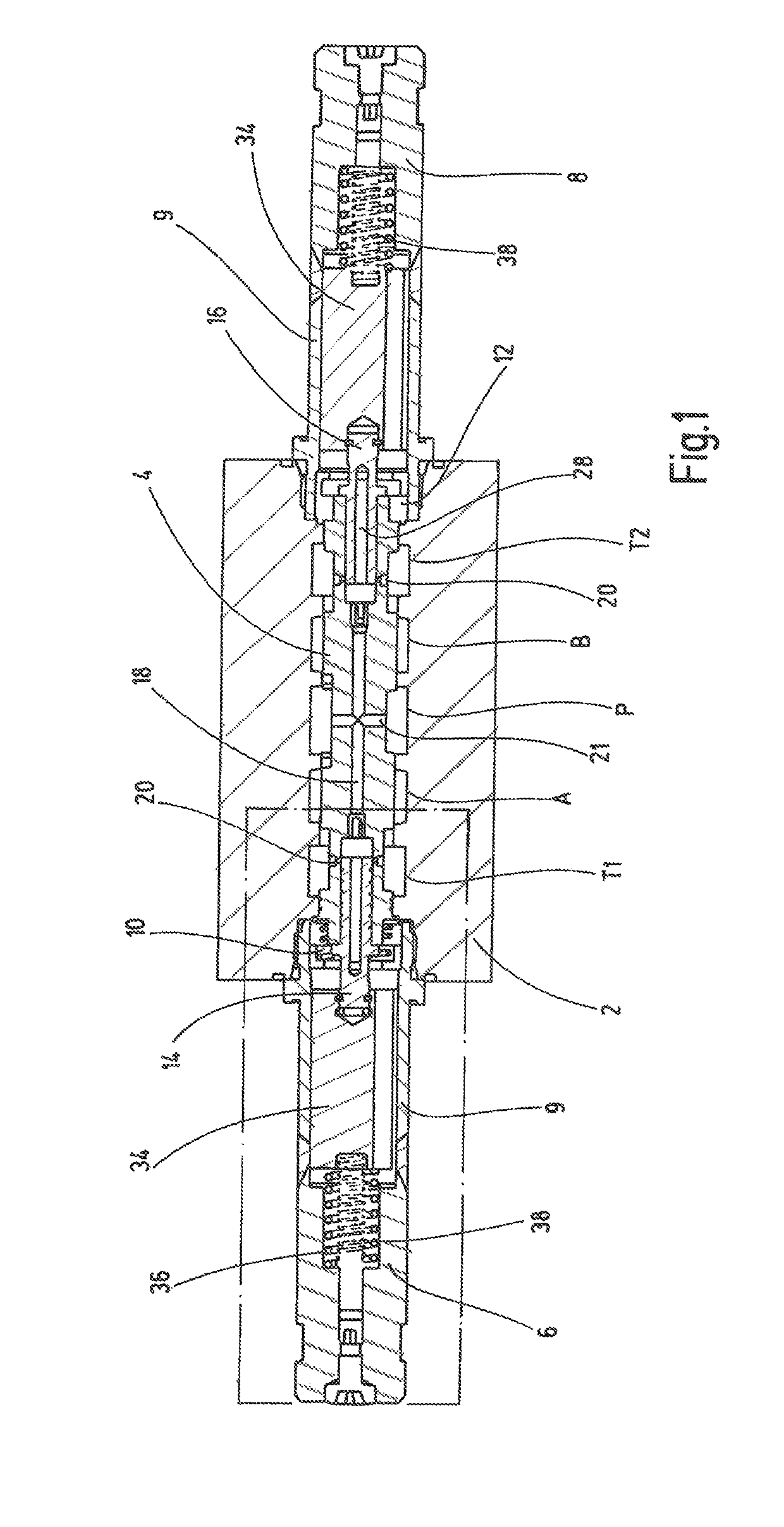
[0015]FIG. 1 depicts, in a schematic, not to scale longitudinal section, a valve device, according to an exemplary embodiment of the invention, for controlling the flow of pressurizing medium, such as hydraulic oil, to a consumer (not depicted in detail). For example, the consumer is in the form of a hydraulic working cylinder, which can be attached to the consumer connections A, B with its piston side and rod side and the two associated working spaces. The valve device has a valve housing 2, which is formed essentially block-shaped and in particular cylindrical. In addition, the valve housing 2 delimits towards the outside the fluid connection points A, B, P, T1, T2, which, in a conventional manner, open into annular channels inside the valve housing 2 and which can be activated by a main piston or a valve piston 4. The two tank connections T1, T2 are brought together at a common tank connection T, so that a fluid discharge both from the tank connection T1 and via the connection T2...


PUM


Abstract

A valve device has a valve housing and a main piston (4) arranged in an axially slidable manner in a piston bore of the valve housing (2). A first consumer connection (A) and a second consumer connection (B) can be alternately connected to a pressure connection (P) and a tank connection (T1, T2) by the action of a first magnetic actuating system (6) and a second magnetic actuating system (8) with two pilot pistons (14, 16). In an actuated state of the respective pilot piston (14, 16), the main piston (4) follows the movement of the pilot piston (14, 16) due to the force ratio adjusting itself to actuate the fluid-carrying connection between the pilot chamber (10, 12) of the pilot piston (14,16) and the assignable tank connection (T1, T2) such that pilot oil flows.

Description

FIELD OF THE INVENTION[0001]The invention relates to a valve device having a valve housing and a main piston arranged in an axially displaceable manner in a piston bore of the valve housing. Via the main piston, a first consumer connection and a second consumer connection can be alternately connected to a pressure connection and to a tank connection by the action of a first magnet actuating system and a second magnet actuating system. The main piston can be displaced out of a centered, preferably central rest position in a first direction for the connection of the first consumer connection to the pressure connection, and of the second consumer connection to the tank connection and can be displaced in an opposite direction for the converse fluid-conducting connection of the connections. A first pilot control compartment is provided and applies a pressure to a first piston rear side of the main piston. A second pilot control compartment is provided and applies a pressure to a second p...

Claims


Application Information

Patent Timeline
IPC IPC(8): F16K11/07F16K31/06
CPCF16K11/0716F16K31/0613Y10T137/8671Y10T137/86702
Inventor SCHULZ, FRANK
Owner HYDAC FLUITECHNIK GMBH
Why Eureka
Try Eureka