Outboard motor and watercraft

a technology for outboard motors and watercraft, which is applied in the direction of marine propulsion, combustion air/fuel air treatment, and vessel construction, etc. it can solve the problems of degrading the efficiency of removing water drops contained in external air, difficult to inhibit the flow rate of external air through the intake duct, and inability to expand the area of the intake duct, etc., to achieve the effect of improving the efficiency of removing water drops

Active Publication Date: 2019-11-05
YAMAHA MOTOR CO LTD
View PDF20 Cites 0 Cited by
  • Summary
  • Abstract
  • Description
  • Claims
  • Application Information

AI Technical Summary

Benefits of technology

[0004]Preferred embodiments of the present invention provide an outboard motor that enhances the efficiency of removing water drops contained in the external air, and a watercraft including the outboard motor.
[0006]According to the preferred embodiments of the present invention disclosed herein, it is possible to provide an outboard motor that enhances the efficiency of removing water drops contained in the external air, and a watercraft including the outboard motor.

Problems solved by technology

However, in the method disclosed in Japan Laid-open Patent Application Publication No. 2008-88881, when the engine cover is designed to have a size equivalent to a type of engine cover designed to contain no intake duct in the gap between the engine and the engine cover, the intake duct must be disposed in a narrow gap, and hence, the area of the intake duct cannot be enlarged.
Therefore, it is difficult to inhibit the flow rate of the external air flowing through the intake duct.
Consequently, the efficiency of removing water drops contained in the external air is degraded.

Method used


Image

  • Outboard motor and watercraft
  • Outboard motor and watercraft
  • Outboard motor and watercraft

Examples


first preferred embodiment

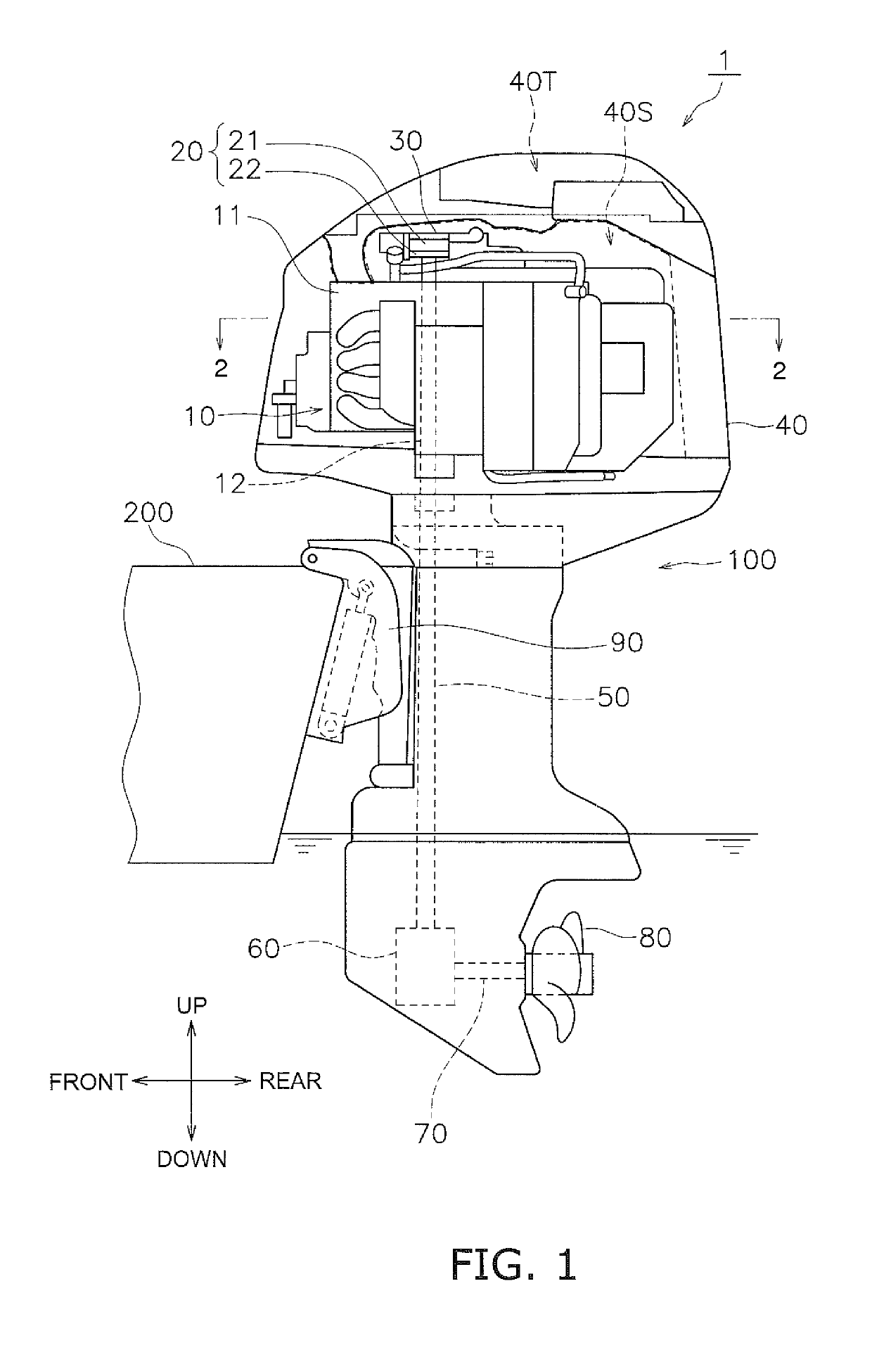
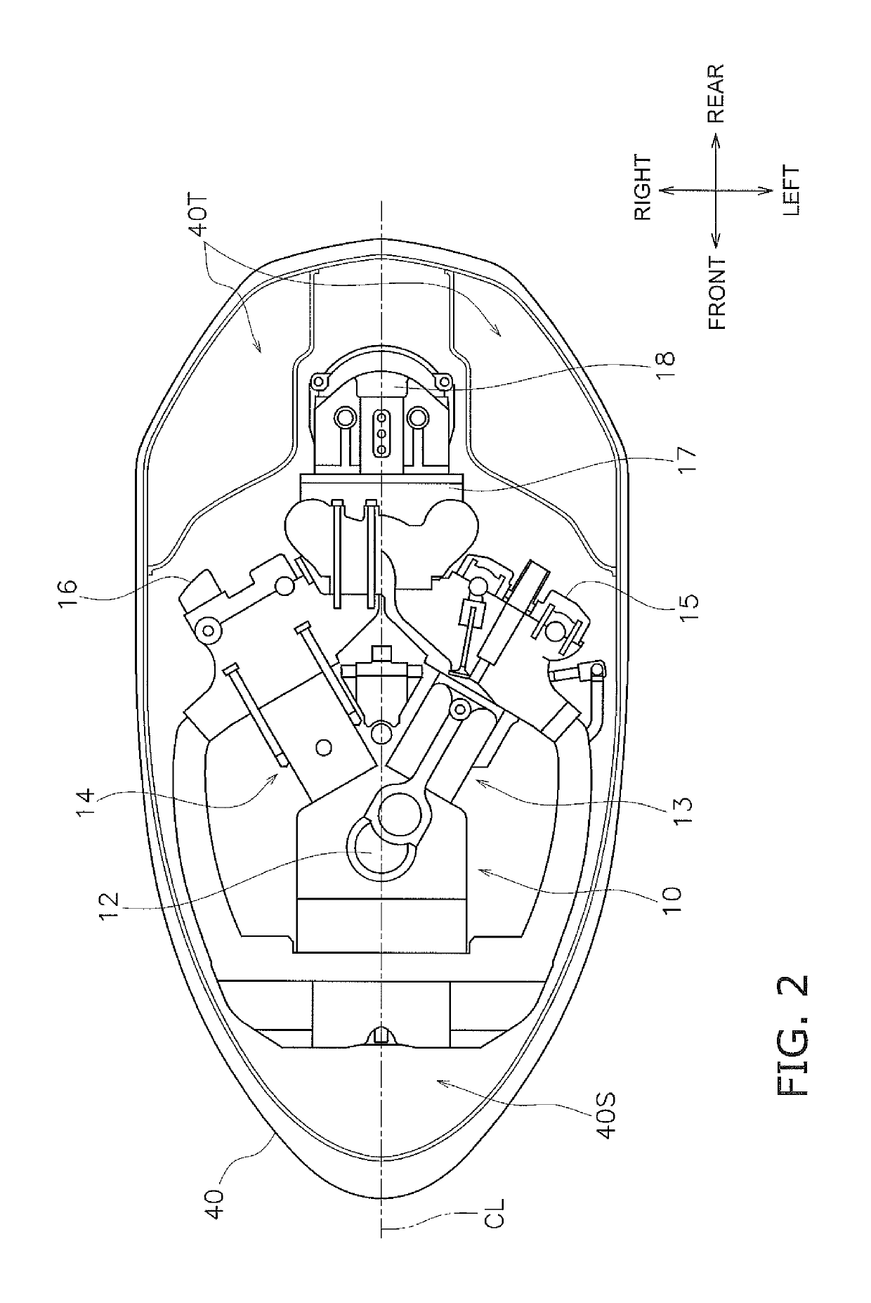
[0026]FIG. 1 is a side view of a watercraft 1 according to a first preferred embodiment of the present invention. As shown in FIG. 1, the watercraft 1 includes an outboard motor 100 and a hull 200. FIG. 2 is a cross-sectional view of FIG. 1 taken along line 2-2.

[0027]The outboard motor 100 is used as a propulsion device for the hull 200. The outboard motor 100 is attached to a rear end of the hull 200. The outboard motor 100 includes an engine 10, a flywheel type magnet generator 20, a fan 30, an engine cover 40, a drive shaft 50, a shift mechanism 60, a propeller shaft 70, a propeller 80, and a bracket 90.

[0028]The engine 10 is preferably a V-type eight-cylinder engine, for example, configured to burn fuel to generate a driving force. The engine 10 is accommodated in an engine compartment 40S provided within the engine cover 40.

[0029]The engine 10 includes a throttle body 11, a crankshaft 12, four first cylinders 13, four second cylinders 14, a first head cover 15, and a second hea...

second preferred embodiment

[0068]An outboard motor according to a second preferred embodiment of the present invention will be explained with reference to the attached drawings. The outboard motor according to the second preferred embodiment is different from the outboard motor 100 according to the first preferred embodiment regarding the construction of the third airflow passage of the intake path. The difference from the first preferred embodiment will be hereinafter explained.

[0069]FIG. 10 is an exploded perspective view of the engine cover 40a according to the second preferred embodiment. FIG. 11 is a schematic diagram of the construction of an intake path 40U according to the second preferred embodiment. The engine 10 is not shown in FIG. 10, whereas the engine 10 and the upper cover 41 are not shown in FIG. 11.

[0070]As shown in FIG. 10, the engine cover 40a includes the upper cover 41, the lower cover 43, the inner lid 44, the first air duct member 45, and a hollow member 48. The upper cover 41, the low...


PUM


Abstract

An outboard motor includes an engine, an engine cover accommodating the engine, and an intake path between the engine cover and the engine. The intake path directs external air to the engine. The engine cover includes an upper cover and a lower cover. The upper cover includes an opening to take external air into the intake path. The intake path includes a first airflow passage, a second airflow passage, and an airflow space. The first airflow passage is at least partially defined by an inner surface of the engine cover, and downwardly directs the external air. The second airflow passage is at least partially defined by the inner surface of the engine cover, and upwardly directs the external air. The airflow space is above the lower cover and continues to the first airflow passage and the second airflow passage.

Description

BACKGROUND OF THE INVENTION1. Field of the Invention[0001]The present invention relates to an outboard motor including an intake path to direct external air to an engine, and to a watercraft including the outboard motor.2. Description of the Related Art[0002]A well-known method, which has been conventionally applied to an outboard motor equipped with an engine and an engine cover that accommodates the engine, includes providing an intake duct to direct external air to the engine in a gap between the engine and the engine cover (see Japan Laid-open Patent Application Publication No. 2008-88881).[0003]However, in the method disclosed in Japan Laid-open Patent Application Publication No. 2008-88881, when the engine cover is designed to have a size equivalent to a type of engine cover designed to contain no intake duct in the gap between the engine and the engine cover, the intake duct must be disposed in a narrow gap, and hence, the area of the intake duct cannot be enlarged. Therefore...

Claims


Application Information

Patent Timeline
Patent Type & Authority Patents(United States)
IPC IPC(8): B63H20/32F02M35/16
CPCB63H20/32F02M35/168
Inventor OCHIAI, KATSUMISATO, TOMOAKIITOU, YASUTAKAMIYAGI, YUTAYAMADA, TAKAYUKI
Owner YAMAHA MOTOR CO LTD
Why Eureka
Try Eureka