Method and apparatus for grid mapping in a wireless communication system
a wireless communication system and wireless communication technology, applied in the field of wireless communication systems, can solve the problems of unprecedented challenges in the future of mobile communication technology, low cost of terminals in mmtc scenarios, and long battery life, so as to achieve low peak-to-average power ratio, high flexibility of selection of multiple access resources, and effective saving power
- Summary
- Abstract
- Description
- Claims
- Application Information
AI Technical Summary
Benefits of technology
Problems solved by technology
Method used
Image
Examples
embodiment 1
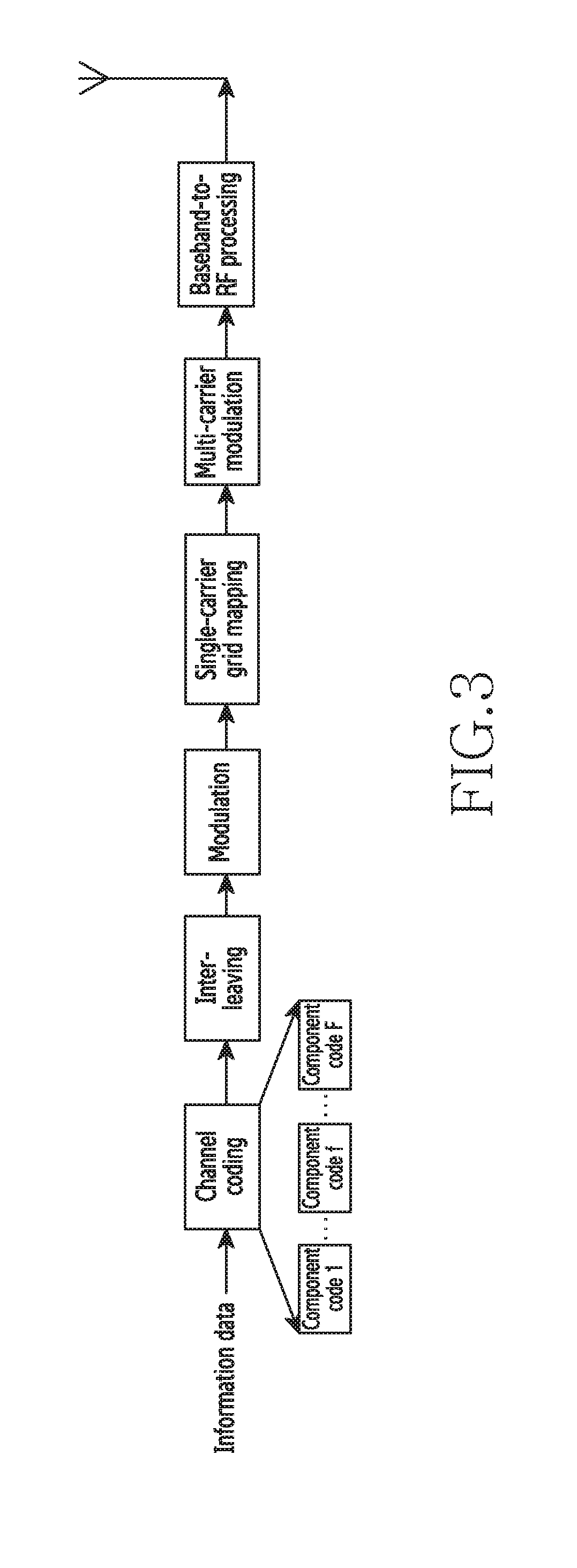
[0075]Based on the principle, referring to FIG. 4, the present disclosure provides an embodiment of a multi-terminal information transmitting method based on grid mapping, comprising the following steps of:
[0076]S11: receiving a configured grid mapping pattern;
[0077]S12: performing channel coding on information data to obtain a corresponding coded sequence;
[0078]S13: performing symbol modulation on the coded sequence to obtain a modulated symbol sequence;
[0079]S14: performing grid mapping on the modulated symbol sequence based on the grid mapping pattern;
[0080]S15: performing multi-carrier modulation on the sequence passing through the grid mapping to obtain a corresponding modulated sequence; and
[0081]S16: performing baseband-to-RF processing on the modulated sequence, and then transmitting the sequence.
[0082]In this embodiment, to describe the method steps more conveniently, the structure of a transmitter for transmitting a terminal signal will be introduced by specific parameters...
embodiment 2
[0133]Correspondingly, referring to FIG. 12, the present disclosure also provides an embodiment of a multi-terminal information receiving method based on grid mapping, comprising the following steps of:
[0134]S21: configuring a grid mapping pattern, and transmitting the grid mapping pattern to each terminal,
[0135]S22: performing RF-to-baseband processing on received information data of each terminal, the information data being superimposed via channels; and
[0136]S23: processing the information data by a multi-terminal joint detector, and distinguishing each terminal based on the grid mapping pattern to determine the information data corresponding to each terminal.
[0137]The method further comprises: configuring a bit-level interleaving pattern and transmitting the bit-level interleaving pattern to each terminal, and distinguishing, by the multi-terminal joint detector, each terminal based on the corresponding bit-level interleaving pattern.
[0138]FIG. 13 is a block diagram of a transmi...
embodiment 3
[0176]In order to further describe the multi-terminal joint detector of Embodiment 2, the structure of a multi-terminal joint detector applicable to the present disclosure and a corresponding detection algorithm will be introduced in this embodiment. The structure of a multi-terminal joint detector in this embodiment is as shown in FIG. 16.
[0177]In FIG. 16, the multi-terminal detector receives signals from a multiple of terminals, which are polluted by channels and noise and superposed, and prior information from a multiple of channel decoders, which is composed of a multiple of terminal information estimations; and outputs posterior information of a multiple of pieces of terminal information, for being used in the subsequent decoding and other steps.
[0178]The multi-terminal detector of the present disclosure is applicable to single-carrier interleave-grid multiple access of the present disclosure, and also applicable to interleave-grid multiple access based on the SC-FDMA waveform....
PUM
 Abstract
Description
Claims
Application Information
 - R&D
- Intellectual Property
- Life Sciences
- Materials
- Tech Scout
- Unparalleled Data Quality
- Higher Quality Content
- 60% Fewer Hallucinations
Browse by: Latest US Patents, China's latest patents, Technical Efficacy Thesaurus, Application Domain, Technology Topic, Popular Technical Reports.
© 2025 PatSnap. All rights reserved.Legal|Privacy policy|Modern Slavery Act Transparency Statement|Sitemap|About US| Contact US: help@patsnap.com


