Device and method for controlling linear motor

a linear motor and control device technology, applied in the direction of motor/generator/converter stopper, dynamo-electric converter control, stopping arrangement, etc., can solve the problem of moving element dropping, and achieve the effect of improving the responsiveness of controlling the linear motor

Active Publication Date: 2019-12-03
THK CO LTD
View PDF10 Cites 6 Cited by
  • Summary
  • Abstract
  • Description
  • Claims
  • Application Information

AI Technical Summary

Benefits of technology

[0013]According to the control device and the control method for the linear motor described above, it is possible to improve responsiveness in controlling the linear motor.

Problems solved by technology

With the linear motor that moves a movable element in the vertical direction, there is a possibility that, when the servo control starts, the movable element may drop due to gravity such that it is displaced from a target position.

Method used


Image

  • Device and method for controlling linear motor
  • Device and method for controlling linear motor
  • Device and method for controlling linear motor

Examples


Embodiment Construction

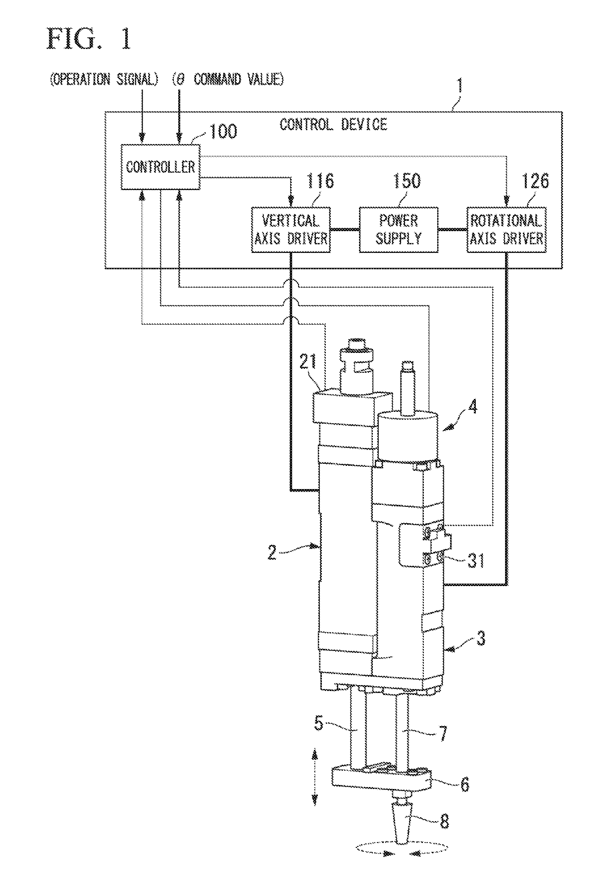
[0021]Hereinafter, a control device and a control method for a linear motor in an embodiment of the present invention will be described with reference to the drawings. FIG. 1 is a diagram showing an outline of a linear actuator in the present embodiment. The linear actuator is used, for example, as a transport device, a pick-and-place device, or a semiconductor processing device. The linear actuator has a control device 1, a linear motion device 2, a rotation device 3, and a brake device 4.

[0022]The linear motion device 2 has a linear motor. The linear motion device 2 linearly moves a rod 5 which is a movable element of the linear motor. A connecting plate 6 is fixed to a tip of the rod 5. The rotation device 3 has a rotary motor. The rotation device 3 rotates a rod 7, which is a movable element of the rotary motor, about a central axis of the rod 7. The rod 7 is rotatable connected to the connecting plate 6 via a bearing (not shown) provided in the connecting plate 6. The rod 7 is ...


PUM


Abstract

A control device for a linear motor includes a speed controller that calculates a current command value by an integration operation using a first integral value of a difference between a moving speed of a movable element provided in the linear motor and a speed command value calculated on the basis of a position command value, a current controller that applies a voltage to the linear motor on the basis of the current command value, and a correction value storage unit that stores the first integral value of the speed controller when the movable element remains at a position indicated by the position command value. When resuming control of the linear motor, the speed controller sets the first integral value stored in the correction value storage unit as an initial value for the integration operation before the brake controller turns off the brake device.

Description

TECHNICAL FIELD[0001]The present invention relates to a control device and a control method for a linear motor.[0002]Priority is claimed on Japanese Patent Application No. 2015-253084, filed Dec. 25, 2015, the content of which is incorporated herein by reference.BACKGROUND ART[0003]A machine tool such as a chip mounter for attaching workpieces to a substrate is used to mount workpieces such as electronic components on a substrate. In the machine tool, a servo-controlled linear motor is used for movement in the vertical direction when attaching a workpiece to a substrate. With the linear motor that moves a movable element in the vertical direction, there is a possibility that, when the servo control starts, the movable element may drop due to gravity such that it is displaced from a target position. There is a technology which prevents displacement of the movable element due to an external force such as gravity at the start of servo control or the like by generating a thrust force fo...

Claims


Application Information

Patent Timeline
Patent Type & Authority Patents(United States)
IPC IPC(8): H02P6/00H02P6/17H02P6/28B65G47/91H01L21/67H02P6/08H02P6/24
CPCB65G47/91H02P6/28H02P6/24H02P6/17H02P6/08H02P6/006H01L21/67144H02K16/00H02K41/02H02K2201/18H02P3/025H02P7/02
Inventor NOMURA, YUKIKARAUSHI, TAKEONAKAYAMA, HIDEYAINDA, TSUYOSHI
Owner THK CO LTD
Why Eureka
Try Eureka