
System and method for water purification

a technology of purification system and water purification method, which is applied in the direction of separation process, evaporator regulation/control, treatment water nature, etc., can solve the problems of clogging and/or damage of filters in the ro system, untold number of human deaths every year, and the need for ongoing maintenance and replacement of filters

Active Publication Date: 2019-12-17
CLOUDBURST SOLUTIONS
View PDF30 Cites 14 Cited by
  • Summary
  • Abstract
  • Description
  • Claims
  • Application Information

AI Technical Summary

Benefits of technology

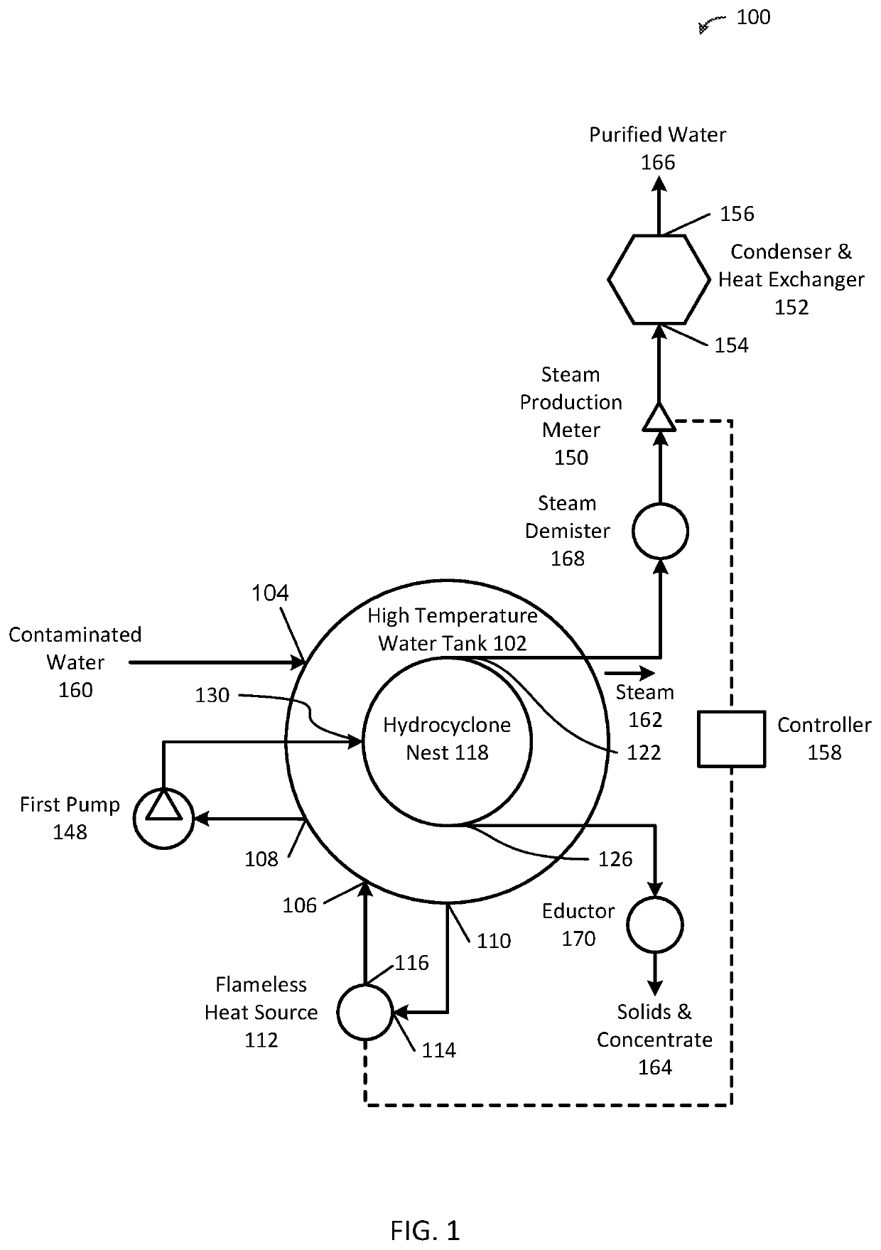
The present invention provides a system and method for purifying contaminated water using a process that separates suspended solids and removes dissolved solids through centrifugal force and a change of phase. The system includes a high temperature water tank, a flameless heat source, a cylindrical vessel with hydrocyclones, a pump, a steam production meter, a steam condenser and heat exchanger, and a steam demister. The method involves heating the contaminated water in the high temperature water tank, pumping the water into the cylindrical vessel with hydrocyclones, and separating the water into steam and solids / concentrate. The technical effects of the invention include efficient purification of contaminated water without the need for filters or chemicals, and the removal of bacteria and VOCs.

Problems solved by technology

An untold number of humans die every year because the water they consume is contaminated.
This process has been around for a long time, but it has its drawbacks.
Although RO systems can be inexpensive, there is an ongoing maintenance requirement of filter replacement.
Filters in RO systems can become clogged and / or damaged by constant exposure to the water source being purified.
Cost and availability of replacement filters and the skill level to perform this maintenance requirement can present a problem.
Although effective when the proper concentrations of chemicals are used, it is difficult to always measure the proper amounts.
In addition, this system of purification does not address problems with heavy metals that may be present in water.
Unfortunately, in many parts of the world where contaminated water is a major problem, the availability of materials to heat water, such as wood, does not exist.
In particular areas or industries, hot water and / or steam may be needed, but it may be critical that no open flames be used to heat the water.
This substance, while commercially useful in the manufacture of coatings, sealants, candles, rubber compounding, pharmaceuticals and cosmetics, can present a problem with regard to the production of oil.
Paraffin suspended in the crude oil tends to clog perforations in the oil well's production string and slows the flow of crude oil to the surface.
Availability of water at the well site is a common problem, and unsafe conditions exist when an open flame, like those used to heat water or crude in the boiler tanks, is positioned near the wellhead where there may be a high concentration of natural gas in the atmosphere.
While this eliminates the open flame close to the wellhead, it can involve a large capital expenditure that may become economically viable only when there is a large concentration of wells in a relatively small area.
This may cause only distilled water to be delivered to the wellhead.
While this method eliminates open flames near the wellhead and does not require large capital expenditures, it does add substantial cost to the operation.
The chemicals are expensive, costs associated with the transportation and handling of hazardous chemicals is expensive, and the addition of these chemicals to the crude oil makes the refining process more expensive.
Another problem that has become of increasing importance is the treatment and / or disposal of produced water and frac water from oil and gas wells due to the large amounts of water required for hydraulic fracturing and public concerns over drinking water contamination.

Method used


Image

  • System and method for water purification
  • System and method for water purification
  • System and method for water purification

Examples


Embodiment Construction

[0029]While the making and using of various embodiments of the present invention are discussed in detail below, it should be appreciated that the present invention provides many applicable inventive concepts that can be embodied in a wide variety of specific contexts. The specific embodiments discussed herein are merely illustrative of specific ways to make and use the invention and do not delimit the scope of the invention. The discussion herein relates primarily to purifying contaminated water (i.e., any water that is not suitable for human consumption), but it will be understood that the concepts of the present invention are applicable to any system and method for treating liquids.

[0030]The present invention provides a system and method of purifying (to drinking water standards) contaminated water, including sea water, oilfield frac water, acid mine run off water, sewage water, etc. utilizing a process to effect separation of suspended solids through centrifugal force and a chang...


PUM

PropertyMeasurementUnit
pressureaaaaaaaaaa
diameteraaaaaaaaaa
diameteraaaaaaaaaa

Abstract

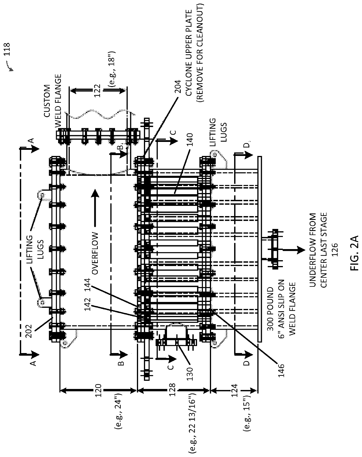
A water purification system includes a high temperature water tank, a flameless heat source, a cylindrical vessel (hydrocyclone nest), a first pump, a steam production meter, and a steam condenser and heat exchanger. The contaminated water is heated within the high temperature water tank using the flameless heat source. The heated contaminated water heats the cylindrical vessel and one or more sets of hydrocyclones. The heated contaminated water is pumped into the cylindrical vessel such that the heated contaminated water enters a tangential inlet of the hydrocyclones, the hydrocyclones separate the heated contaminated water into steam and solids / concentrate, the steam exits through an overflow of the hydrocyclones and a first outlet of the cylindrical vessel, the solids / concentrate exit through an underflow of the hydrocyclones and a second outlet of the cylindrical vessel. The steam is condensed into purified water using the steam condenser and heat exchanger.

Description

CROSS-REFERENCE TO RELATED APPLICATIONS[0001]The patent application claims priority to and is a non-provisional application of U.S. provisional patent application Ser. No. 62 / 083,143 filed on Nov. 21, 2014, which is hereby incorporated by reference in its entirety.INCORPORATION-BY-REFERENCE OF MATERIALS FILED ON COMPACT DISC[0002]None.TECHNICAL FIELD OF THE INVENTION[0003]The present invention relates generally to the field of heating liquids and, more particularly, to a system and method for purifying water.STATEMENT OF FEDERALLY FUNDED RESEARCH[0004]None.BACKGROUND OF THE INVENTION[0005]As described in U.S. Pat. Nos. 7,866,380 and 7,959,814, one of the most pressing needs throughout the world is drinkable water. An untold number of humans die every year because the water they consume is contaminated. In some areas, people are forced to spend a great deal of time manually hauling water from a distant source to their homes and villages rather than taking the risk of drinking unteste...

Claims


Application Information

Patent Timeline
Patent Type & Authority Patents(United States)
IPC IPC(8): C02F1/04B01D1/30C02F1/16B01D19/00B01D21/26C02F1/38B01D1/00C02F103/00C02F103/02C02F103/08C02F103/10C02F103/36
CPCB01D1/0094B01D19/0057B01D1/0082C02F1/048B01D1/305C02F1/16B01D1/0058C02F1/38B01D21/267C02F2209/40C02F2103/008C02F2103/023C02F2103/08C02F2103/001C02F2201/008C02F2209/38C02F2103/365C02F2201/005C02F2209/02C02F2103/10C02F1/18C02F1/20Y02A20/124C02F1/02B04C9/00
Inventor WILSON, EDWIN E.
Owner CLOUDBURST SOLUTIONS
Learn More