Computed tomography having motion compensation

a computed tomography and motion compensation technology, applied in the field of computed tomography having motion compensation, can solve the problems of non-rigid movement and preventing consistent image reconstruction, and achieve the effect of low deformation, effective compensation and iterative optimization convergent particularly quickly

Active Publication Date: 2019-12-24
SIEMENS HEALTHCARE GMBH
View PDF12 Cites 2 Cited by
  • Summary
  • Abstract
  • Description
  • Claims
  • Application Information

AI Technical Summary

Benefits of technology

[0014]It is the case also in the method according to one embodiment that a volume model is computed on the basis of a plurality of projections which are generated at different projection angles. During the reconstruction of the beam profile, the sensor position of each beam sensor is corrected for at least one projection angle by at least one correction vector. As is known from the prior art, each correction vector is designed to describe or to compensate for the deviation of the position of the projection surface from the planned movement trajectory. What is achieved in a known manner by way of the correction vectors is that a volume model is generated on the basis of the corrected sensor position, which volume model meets a predetermined optimization criterion. The image properties are thus improved with respect to a volume model computed from non-corrected sensor positions (i.e., for example the imaging distortion is reduced).
[0030]With respect to the division of the total projection surface into the described partial surfaces, the method according to one embodiment is very flexible. It is even possible to recreate curved, oval or saddle-shaped detectors in a simple manner by planar partial surfaces and the volume model, which on the basis of projections that were obtained with such detectors, can likewise be optimized iteratively in the described manner by the correction vectors and matched to the detector form, without the detector form having to be previously known at all.
[0032]However, also provided is preferably a division into a plurality of partial surfaces within a closed detector surface. As a result, in addition to the relatively low deformation of the detector itself, the non-rigid movement of the body volume, that is to say its deformation, is then also effectively compensated for.
[0033]A further embodiment of the method also takes into account the special case that the body or the projection surface carries out an actual rigid movement, that is to say either all volume elements or all radiation sensors effect the same translational or linear movement. In order that not every correction vector of the partial surfaces needs to be matched correspondingly identically in a complicated manner in one or more iteration steps to compensate for the rigid movement, the development provides that for at least one projection angle, at least one further correction vector is additionally ascertained for a source position of the radiation source and / or for an object position of the body volume and the volume model is computed therewith. As a result, the rigid movement can be compensated for by matching a single displacement vector, as a result of which an iterative optimization can converge particularly quickly.

Problems solved by technology

What is not possible in the prior art is the compensation of flexible, non-rigid movements, that is to say deformations, of a body volume.
Such non-rigid movements prevent a consistent image reconstruction.

Method used


Image

  • Computed tomography having motion compensation
  • Computed tomography having motion compensation
  • Computed tomography having motion compensation

Examples


Embodiment Construction

[0048]The exemplary embodiments explained below are preferred embodiments. In the exemplary embodiments, however, the described components of the embodiments in each case represent individual features that should be regarded independently of one another, and which in each case also further develop the invention independently from one another and thus should be considered, even individually or in another combination than the one shown, as being a constituent part of the invention. Furthermore, the described embodiments can also be supplemented by further ones of the already described features.

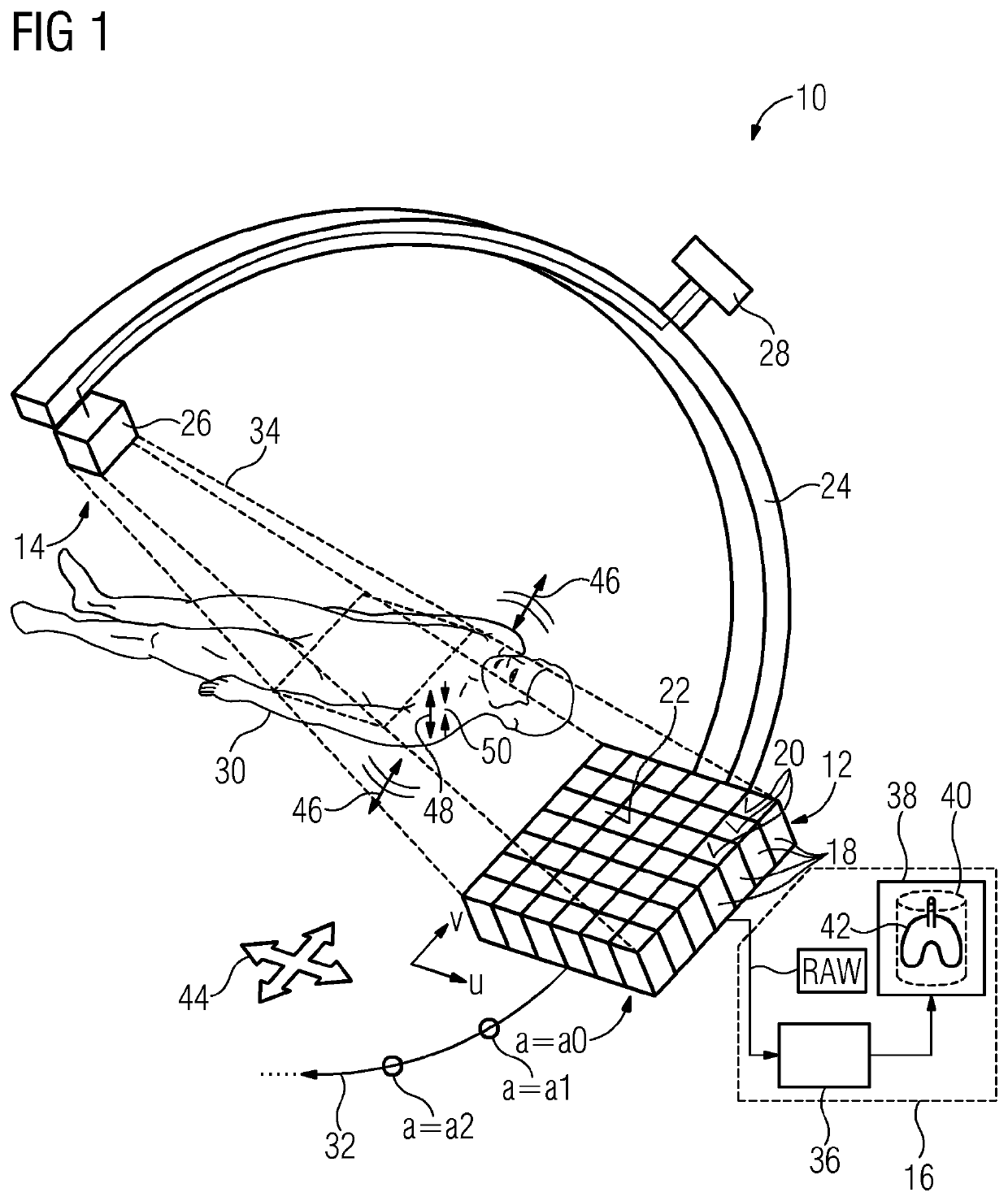
[0049]FIG. 1 shows a tomography system 10, which can be for example an X-ray C-arm system. The tomography system 10 can include a sensor device 12, a projection device 14 and an image generation device 16.

[0050]The sensor device 12 can include a detector having a plurality of radiation sensors 18, of which only some have reference signs in FIG. 1 for the sake of clarity. Sensor entry surfaces 20...


PUM


Abstract

The embodiments relate to a method for producing a digital volume model of a body volume by a sensor device, which sensor device includes a plurality of radiation sensors, of which each produces a pixel value in a projection. In order to produce the volume model, a plurality of projections from different projection angles (a) are produced and the volume model is computed from sensor positions of the radiation sensors and pixel values of the radiation sensors. For at least one projection angle (a), the sensor positions are corrected by a respective correction vector for rigid motion compensation. The problem addressed is that of also compensating the non-rigid motion of the body volume (i.e., the deformation) in the computation of the volume model. This problem is solved in that, in order to correct the sensor positions, the projection surface provided by the totality of the radiation sensors is divided into a plurality of sub-surfaces and a separate correction vector is determined for each of the sub-surfaces independently of each other.

Description

RELATED CASES[0001]The present patent document is a § 371 nationalization of PCT Application Serial Number PCT / EP2013 / 067911, filed Aug. 29, 2013, designating the United States, which is hereby incorporated by reference.BACKGROUND[0002]The present embodiments relate to a tomography system and a method for generating a volume model of a body volume. The volume model can be used to generate, for example, a volume graphic of the body volume, that is to say for example of the interior of a patient's body. The volume model is formed on the basis of pixel values of a plurality of projections of the body volume, wherein the projections are generated on a projection surface from different projection angles. When computing the volume model from the projections, a motion performed by the body volume between the times of projection is compensated. The tomography system according to one embodiment may be designed, for example, as an X-ray-based computed tomography scanner.[0003]In order to gene...

Claims


Application Information

Patent Timeline
Patent Type & Authority Patents(United States)
IPC IPC(8): A61B6/00A61B6/03
CPCA61B6/585A61B6/5264A61B6/032A61B6/582
Inventor KYRIAKOU, YIANNIS
Owner SIEMENS HEALTHCARE GMBH
Why Eureka
Try Eureka