
Trajectory determination method for non-productive movements

a non-productive movement and trajectory determination technology, applied in the direction of programmed manipulators, programme control, instruments, etc., can solve the problems of requiring considerable computing power, and achieve the effect of reducing vibration stresses on the machine tool, rapid traversing of the tool, and excessive wear of the machine tool

Active Publication Date: 2019-12-24
SIEMENS AG
View PDF23 Cites 0 Cited by
  • Summary
  • Abstract
  • Description
  • Claims
  • Application Information

AI Technical Summary

Benefits of technology

The invention provides a method for optimizing a second trajectory and an instruction set for a non-productive movement in a machine tool. The method uses the starting and end positions of the non-productive movement as input and can quickly establish an optimized second trajectory with low computing power. The method is adaptable to the operating parameters of the machine tool and can be executed in real-time. The invention also provides a program that can be executed on a variety of control units for machine tools and requires little computing power. The technical effects of the invention include improved machine tool operation, reduced downtime in production processes, and increased economic viability.

Problems solved by technology

One disadvantage of known machine control methods is that they are based on an extensive data record of the tool's surroundings, the provision and processing of which during machine operation requires considerable computing power.

Method used


Image

  • Trajectory determination method for non-productive movements
  • Trajectory determination method for non-productive movements
  • Trajectory determination method for non-productive movements

Examples


second embodiment

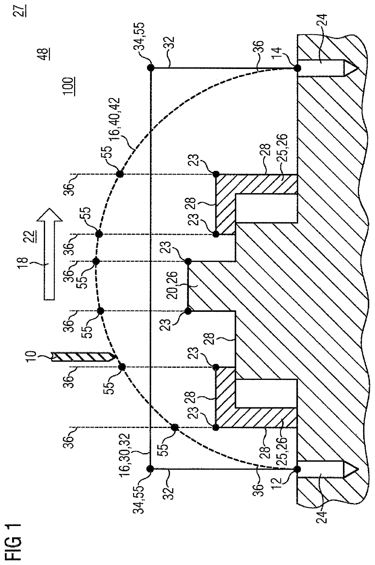
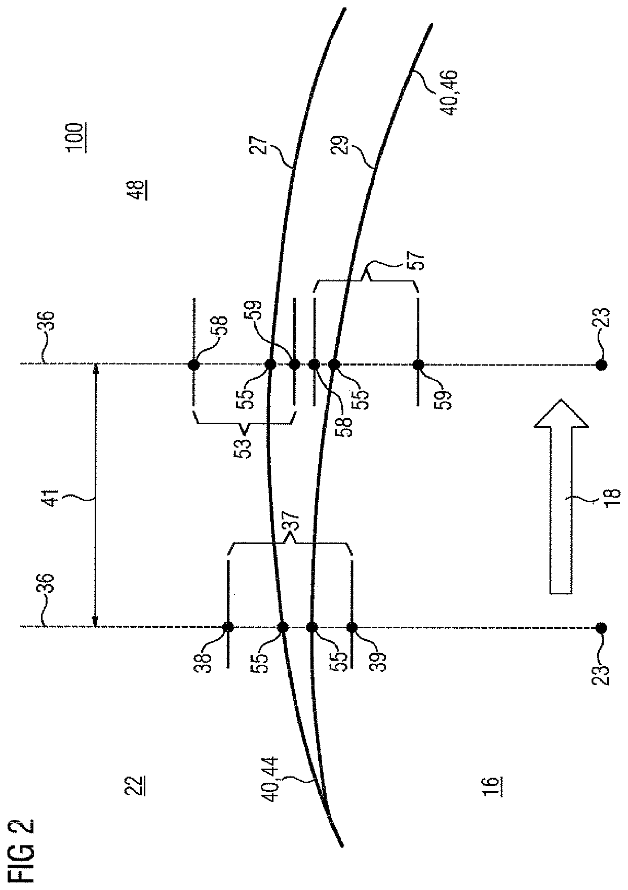
[0028]FIG. 2 shows a portion of the method 100 according to the invention in which the algorithm 48, which is not shown in greater detail, is called in a plurality of runs 44, 46. The embodiment shown serves to perform a non-productive movement of a tool 10 in a machine tool 50. The method 100 is performed in a travel envelope 22 in which obstacles 26, which are not shown in greater detail, with an obstacle contour 28 and edges 23 are arranged. The travel envelope 22 here takes substantially the same form as the travel envelope 22 in FIG. 1. In the first run 44, the algorithm 48 establishes a second trajectory 40 which is based on a model 27 of the travel envelope 22 with control planes 36 with target corridors 37, 53.

[0029]The method 100 in FIG. 2 is a two-dimensional projection of a three-dimensional movement. The control planes 36 each end at an edge 23 which is part of an obstacle 26 in the travel envelope 22. A first target corridor 37, which is defined by first and second corr...

third embodiment

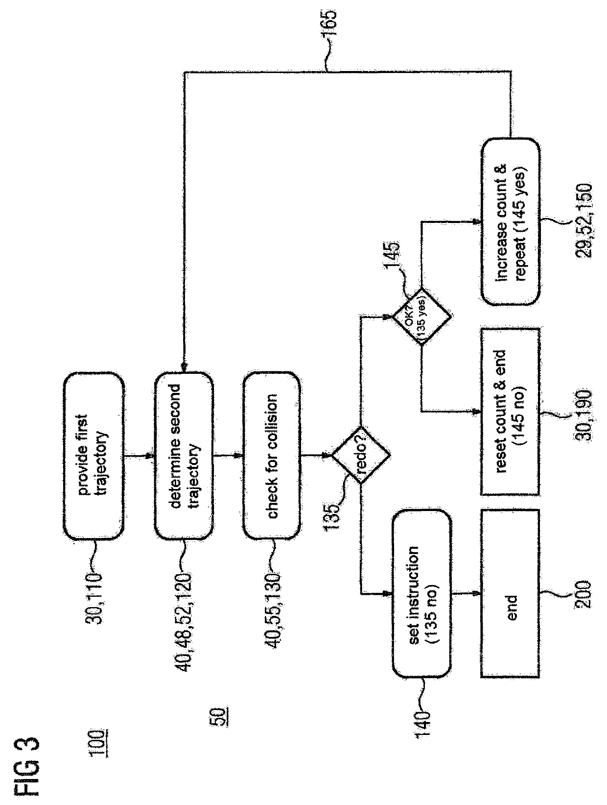
[0031]FIG. 3 shows a sequence diagram of the method 100 according to the invention. The embodiment shown serves to perform a non-productive movement of a tool 10 in a machine tool 50. A provision step 110 provides a first trajectory 30 for the non-productive movement 16 to be performed, such as for example in FIG. 1. This proceeds, for example, by a first trajectory 30 input manually by a user for a algorithm 48 being loaded from an electronic storage device. In a subsequent optimization step 120, the provided first trajectory 30 is further processed by means of the algorithm 48 and a second trajectory 40 optimized for at least one target parameter is established. An iteration counter 52 which represents the number of runs of the optimization step 120 is initialized in a first run of the optimization step 120. The second trajectory 40 established in the optimization step 120 leads from the same starting position 12 to the same target position 14 as the first trajectory 30. In a furt...


PUM


Abstract

A method of controlling a non-productive movement of a tool from a starting position to an end position in a travel envelope of a machine tool includes the steps of a) providing a collision-free first trajectory for the non-productive movement of the tool, b) determining a second trajectory that is improved over the first trajectory with regard to a selectable target parameter using an algorithm, and c) checking the second trajectory for collisions and, if the second trajectory is free of collisions, providing an instruction corresponding to the second trajectory. The first trajectory in step a) includes plural rectilinear segments and the second trajectory in step b) includes a polynomial segment and, if the second trajectory is not free of collisions in step c), steps b) to c) are repeated so that the algorithm is provided with a modified model of the travel envelope in a repeat of step b).

Description

CROSS-REFERENCES TO RELATED APPLICATIONS[0001]This application is the U.S. National Stage of International Application No. PCT / EP2016 / 063177, filed Jun. 9, 2016, which designated the United States and has been published as International Publication No. WO 2017 / 005453 and which claims the priority of European Patent Application, Serial No. 15176105.3, filed Jul. 9, 2015, pursuant to 35 U.S.C. 119(a)-(d).BACKGROUND OF THE INVENTION[0002]The invention relates to a method for determining a trajectory for a non-productive movement of a machine tool as well as to a program suitable therefor and to an associated control unit for the machine tool.[0003]DE 103 43 611 A1 discloses a method for machine control in which a working envelope is divided into discrete elements. A binary collision parameter for a tool is provided for each discrete element. When a tool passes through a discrete element during a movement, a collision risk is identified by reference to a lookup table. The tool itself is...

Claims


Application Information

Patent Timeline
IPC IPC(8): B25J9/16G05B19/4061
CPCB25J9/1666G05B19/4061G05B2219/39361G05B2219/40476
Inventor BRETSCHNEIDER, JOCHENLINKE, HARTMUT
Owner SIEMENS AG
Learn More