Inverting thrombectomy apparatuses and methods

a thrombus and thrombosis technology, applied in the mechanical field, can solve the problems of insufficient or irregular blood flow, insufficient blood flow through blood vessels, and shortage of oxygen-carrying red blood cells, and achieve the effects of preventing jamming, preventing jamming, and increasing resistan

Active Publication Date: 2019-12-31
STRYKER CORP
View PDF152 Cites 4 Cited by
  • Summary
  • Abstract
  • Description
  • Claims
  • Application Information

AI Technical Summary

Benefits of technology

[0015]Described herein are methods and apparatuses for improving and enhancing deployment, and particularly in situ deployment, of the apparatus so that the distal end (tip) of the catheter can be deployed distally between the free tractor end and a puller / pusher to which the other end of the tractor is attached and inverted.
[0035]In any of the apparatuses described herein, the elongate inversion support catheter may be adapted to enhance rolling of the tractor region (inverting) over the distal end. For example, in any of the apparatuses described herein, the catheter may be configured so that the material hardness of the catheter decreases over the distal end of the catheter until the distal end opening, wherein the distal end opening has a material hardness that is greater than a material hardness of a region immediately proximal to the distal end, further wherein the distal end opening has a rounded lip profile. The catheter distal end may be stiffer because it is thicker (e.g., it may be formed by inverting the distal end of the catheter back over itself, and / or it may be formed of a stiffer material than the adjacent more proximal region (including by including a reinforcing material).
[0040]Any of the apparatuses described herein may be configured so that the tractor is highly soft, and therefore rolls around the distal end of the catheter forming the elongate inversion support easily without jamming and / or requiring a large force to roll the tractor over the distal end opening of the catheter. In particular, tractors having a low axial compression strength, that would, but for the elongate inversion support, typically buckle, have been found to prevent jamming of the elongate inversion support as the tractor inverts. In particular, unsupported tractors (e.g., tractor that are not rolling over a catheter supported annular opening) that are configured to collapse radially under an axial compression of less than about 500 g of force (e.g., less than: about 500 g force, about 400 g force, about 300 g force, about 200 g force, about 150 g force, about 100 g force, about 50 g force, etc.) may be particularly helpful in preventing jamming. For most knitted, woven, and braided tractors, including those described herein, when the tractor is configured to withstand greater that this amount of axial compression force, the tractor may jam, and / or may require excessive force to invert. Thus, in any of the apparatuses and methods described herein, the tractor maybe sufficiently soft such that without support from the catheter, the tractor collapses radially under an axial compression of less than 200 g of force when inverting (and may instead buckle).
[0041]Further, in any of the apparatuses described herein, the tractor may be biased to expand to greater than the outer diameter of the catheter in a second configuration (that is inverted relative to the first configuration) where the tractor is extending over the outer diameter of the catheter. The same tractor may be biased to expand to greater than the inner diameter of the catheter of the elongate inversion support in the first (e.g., un-inverted), configuration where the tractor is within the catheter of the elongate inversion support. Thus, in relaxed configuration, prior to assembling with the elongate inversion support, the tractor may be oversized compared to the catheter of the elongate inversion support; the portion of the tractor that extends within the catheter of the elongate inversion support, referred to as “un-inverted,” may have an inner diameter that is greater than the inner diameter of the catheter, which may tend to drive the tractor toward the walls of the inner diameter of the catheter without collapsing down into the catheter. Further, the inner diameter of the tractor in the “inverted” configuration, e.g., the configuration of the portion that is doubled back over and along the catheter of the elongate inversion support, may be greater than the outer diameter of the catheter of the elongate inversion support. This arrangement may prevent jamming and an increased resistance between the tractor and the outside of the catheter of the elongate inversion support. The catheter may be biased to expand in both the inverted and un-inverted configurations by, e.g., heat setting. The tractor may be inverted to transition between the first and second configurations by rolling over the distal end of the catheter; the terms “inverted” and “un-inverted” are therefore relative terms.
[0042]The annular bias may be biased to have an expanded, open configuration that has a slightly larger (e.g., greater than 5%, greater than 10%, greater than 15%, greater than 20%, greater than 25%, etc., larger than the expanded diameter of the flexible tractor tube. In addition, the annular bias may be relatively “stiffer” than the open (free) end of the flexible tractor tube, to prevent buckling, collapse, etc. In some variations, the annular bias has a smooth and / or curved edge to prevent getting caught on the elongate inversion support catheter when it is inserted into the annular bias.

Problems solved by technology

Many vascular problems stem from insufficient blood flow through blood vessels.
One causes of insufficient or irregular blood flow is a blockage within a blood vessel referred to as a blood clot, or thrombus.
If one of the coronary arteries is 100% thrombosed, the flow of blood is stopped in that artery, resulting in a shortage of oxygen carrying red blood cells, e.g., to supply the muscle (myocardium) of the heart wall.
Such a thrombosis is unnecessary to prevent loss of blood but can be undesirably triggered within an artery by damage to the arterial wall from atherosclerotic disease.
Similarly, thrombosis of one of the carotid arteries can lead to stroke because of insufficient oxygen supply to vital nerve centers in the cranium.
Oxygen deficiency reduces or prohibits muscular activity, can cause chest pain (angina pectoris), and can lead to death of myocardium which permanently disables the heart to some extent.
If the myocardial cell death is extensive, the heart will be unable to pump sufficient blood to supply the body's life sustaining needs.

Method used


Image

  • Inverting thrombectomy apparatuses and methods
  • Inverting thrombectomy apparatuses and methods
  • Inverting thrombectomy apparatuses and methods

Examples


Embodiment Construction

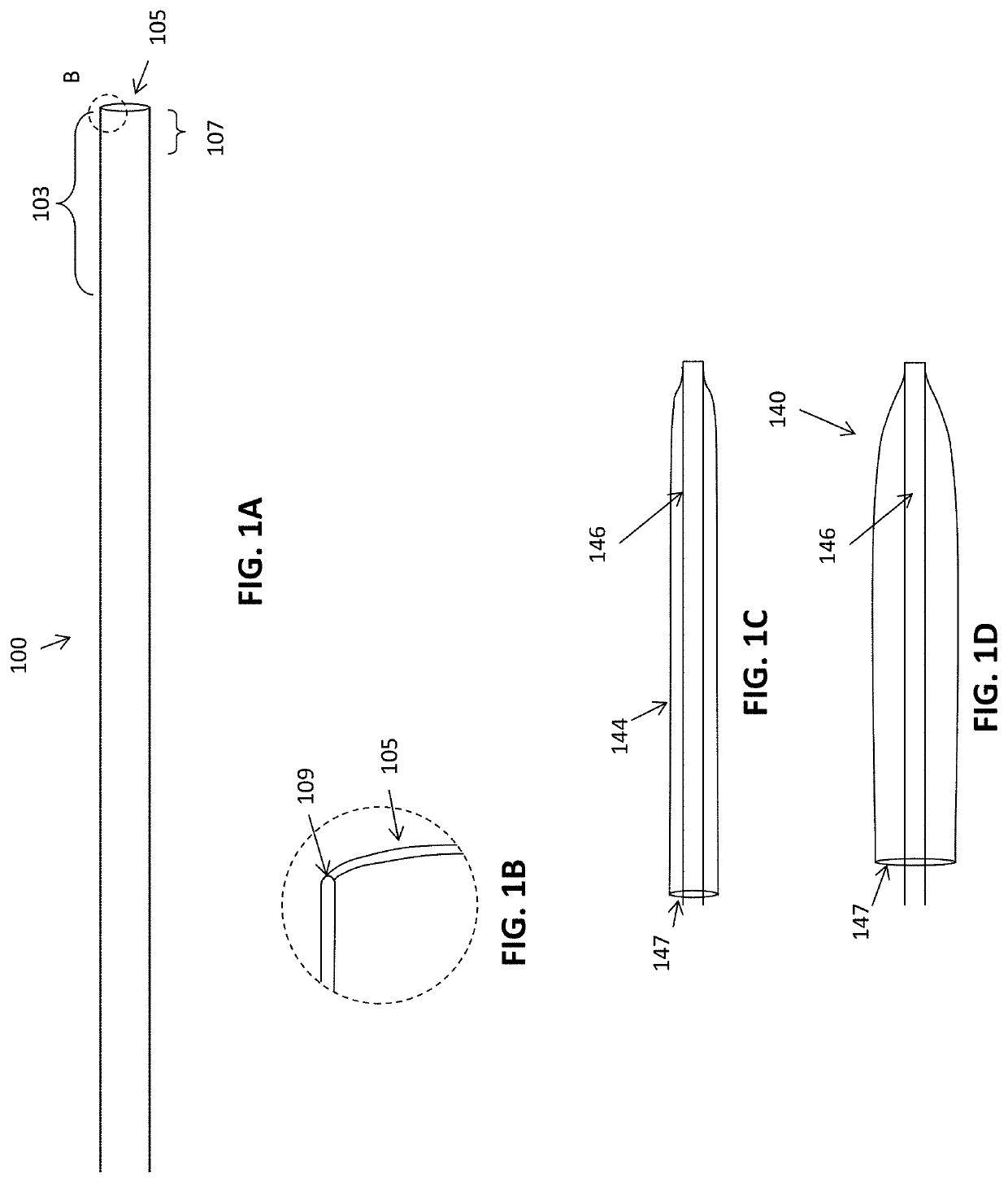
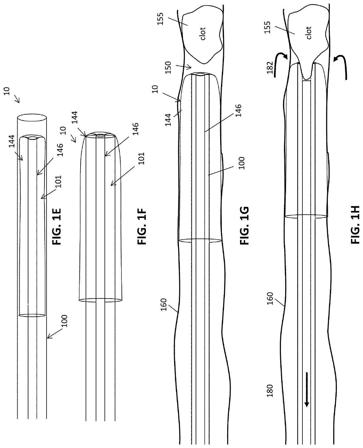
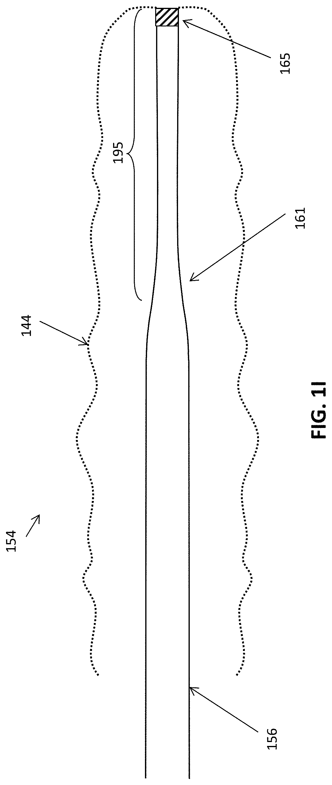
[0056]In general, described herein are mechanical thrombectomy apparatuses having an inverting flexible tractor tube that is configured to be deployed in situ (e.g., within a catheter) without jamming. Any of these apparatuses may include an elongate elongate inversion support catheter over which the flexible tractor tube inverts at the distal end. In the deployment configuration, the flexible tractor tube may comprise a flexible tube that doubles back (e.g., inverts) over the distal end opening of the elongate inverting support catheter so that the tractor tube extends into the opening of the elongate inverting support catheter when the tractor tube is pulled proximally. The tractor tube may be attached at one end to an elongate puller. Pulling the elongate puller proximally will roll and invert the tractor over the distal end opening of the elongate inverting support catheter which may capture a clot and pull it into the elongate inversion support catheter.

[0057]Any of the apparat...


PUM


Abstract

Rolling tractor tube mechanical thrombectomy apparatuses that may be deployed from out of a catheter in situ are described herein. These apparatuses may be delivered out of a catheter from a collapsed delivery configuration within the catheter to a deployed configuration out of the catheter, in which the same catheter is re-inserted between a tubular tractor and an elongate puller. In particular, any of these methods and apparatuses may be adapted to work with a tractor tube having an open end that is biased open, including using an annular bias.

Description

CROSS REFERENCE TO RELATED APPLICATIONS[0001]This patent application claims priority to U.S. provisional patent application No. 62 / 345,152, filed on Jun. 3, 2016, and titled “DOZER THROMBECTOMY SYSTEM 2”.[0002]This patent application may be related to U.S. patent application Ser. No. 15 / 291,015, filed on Oct. 11, 2016, titled “MECHANICAL THROMBECTOMY APPARATUSES AND METHODS”, which is a continuation of U.S. patent application Ser. No. 15 / 043,996, filed Feb. 15, 2016, now U.S. Pat. No. 9,463,035, which claims priority to each of the following provisional patent applications: U.S. Provisional Patent Application No. 62 / 284,300, filed Sep. 28, 2015; U.S. Provisional Patent Application No. 62 / 284,752, filed Oct. 8, 2015; and U.S. Provisional Patent Application No. 62 / 245,560, filed Oct. 23, 2015.[0003]Each of these patents and patent applications is herein incorporated by reference in its entirety.INCORPORATION BY REFERENCE[0004]All publications and patent applications mentioned in this ...

Claims


Application Information

Patent Timeline
Patent Type & Authority Patents(United States)
IPC IPC(8): A61B17/221A61F2/90A61B17/22A61F2/82A61B17/00A61B17/34
CPCA61B17/22032A61B17/221A61B17/22031A61F2/90A61F2002/825A61B2017/2215A61B2017/00349A61B2017/3435A61B2017/22038A61B2017/00867A61B2017/00778A61F2230/0056A61B17/3207A61B17/22A61M25/0119A61M25/0074A61M25/0043A61M25/0021A61B2017/320056A61B2017/22001A61B2017/22072A61M2025/0175A61M2210/12A61M2210/005
Inventor WALLACE, MICHAEL P.GREENHALGH, E. SKOTT
Owner STRYKER CORP
Why Eureka
Try Eureka