Positive crankcase ventilation gas diversion and reclamation system

a technology of ventilation gas and crankcase, which is applied in the direction of liquid fuel feeders, machines/engines, electric control, etc., can solve the problems of premature engine failure, reducing engine efficiency, and unforeseen drawbacks of gdi engines, so as to reduce noxious emissions to the environment, improve air quality, and eliminate carbon buildup

Active Publication Date: 2020-01-07
MESA GILBERTO
View PDF35 Cites 0 Cited by
  • Summary
  • Abstract
  • Description
  • Claims
  • Application Information

AI Technical Summary

Benefits of technology

[0011]It is an object of the present invention to provide air to an intake manifold that is free of oil laden PCV gas contaminants. It is a further object of the present invention to provide intake air free of oil laden PCV gas contaminants that will eliminate the carbon buildup in the intake airway passages in GDI engine, therefore, providing a total solution to the problem. Another object of the present invention is to improve air quality by reducing noxious emissions to the environment.
[0012]It is also an object of the present invention to improve engine performance and prevent the degradation of the intended fuel efficiency over the useful life of a GDI engine.
[0013]A further object of the present invention is to reduce noxious emissions of CO2, NO2, and HC, among others, from low-speed pre-ignition (“LSPI”), also known as stochastic pre-ignition (“SPI”).
[0014]Yet another object of the present invention is to reduce or eliminate the need for toxic and / or cancer causing agents currently used to remove carbon deposits from the internal component of a GDI engine, including, by way of example only, benzene and carbon tetrachloride, and human contact therewith.
[0015]An additional object of the present invention is to relieve consumers from dramatic unnecessary expenses on general vehicle operating costs, estimated to be $800 to $1,500 per 75,000 miles driven per vehicle on naturally aspirated GDI engines.
[0020]The present invention is further directed to a method for reducing positive crankcase ventilation gas emissions during operation of an internal combustion engine assembly. In accordance with at least one embodiment, the present method comprises: diverting an amount of oil laden positive crankcase ventilation gases from the air intake manifold of an internal combustion engine; diffusing the oil laden positive crankcase ventilation gases through an oil-vapor diffuser; diluting the diffused positive crankcase ventilation gases into an amount of liquid fuel; and, supplying an amount of fuel enriched vapor from a headspace of a fuel tank to the air intake manifold of the internal combustion engine.

Problems solved by technology

A significant and apparently unforeseen drawback to a GDI engine is the buildup of carbon deposits on and around the valves due to oil, fuel components, and other particulates and / or contaminants in the positive crankcase ventilation (“PCV”) gasses which are routed directly into the air intake manifold of these GDI engines.
This carbon buildup results in reduced engine efficiency, thus defeating the purpose, increased emissions of noxious combustion byproducts, and more importantly, the carbon buildup eventually result in premature engine failure.
Further, it is estimated that a GDI engine will lose about one percent of its power output for every one thousand miles of use, as a result of the aforementioned carbon deposits.
Every vehicle with a GDI engine will suffer from obstructive carbon buildup due to PCV gas contamination, resulting in significant and unnecessary expense to vehicle owners.
The cost for this problem is staggering, estimated to be between $800 and $1,500 each 30,000 miles for a turbo GDI engine, adding additional and unnecessary expenses over the life of the vehicle to about $4000.
Carbon buildup in GDI engines is an epidemic to the consumer and the environment.
It results in additional and unnecessary financial and environmental consequences that continue to repeat itself over the life of the vehicle.
Among the problems observed in GDI engines are: GDI engines suffer from obstruction of airway passages due to carbon buildup from the oil laden PCV gasses routed into the air intake manifold, which subsequently results in a reduction in efficiency and power, and increased emissions over time; oil laden PCV gases contaminate the incoming air and cause inconsistent air / fuel mixture; contamination of air intake with oil droplets and carbon causes unpredictable ignition in the combustion chamber, commonly known as low-speed pre-ignition (“LSPI”); and, carbon buildup is the direct result of oil laden PCV gases in the engine intake components, prohibiting proper air flow and improper valve seating, among other problems.
This buildup, at a minimum, results in significantly reduced operation efficiency, thereby defeating the purpose of the direct fuel injection system.
More importantly, in many cases the carbon buildup leads to premature catastrophic engine failure, thus requiring replacement or rebuilding, at considerable expense to the owner.
Various methods of cleaning carbon buildup from valves and valve stems, such as is shown in the photograph in FIG. 2, have been proposed, but none are believed to be more than nominally effective, and all are extremely time and labor intensive, and thus, expensive for the owner to undertake.
As will be appreciated, this results in a decrease in efficiency, relative to an engine having direct fuel injection itself, with the further disadvantage of the considerable added expense of building an engine having multiple fuel injectors and the corresponding control systems for the same.
Furthermore, this solution does not readily lend itself to the retrofit of an engine originally equipped solely with direct fuel injection.
A further problem with operation of an internal combustion engine, regardless of whether it employs indirect fuel injection, direct fuel injection, or a combination of the two, is that a certain amount of crankcase oils entrained in the positive crankcase ventilation gases enter the combustion chamber.
Unfortunately, combustion of crankcase oils is much less than complete, leading to an increase in harmful emissions, as well as a corresponding decrease in fuel efficiency.
This problem is exacerbated as carbon buildup from baked on oil residue begins to occur on the valves, valve stems, and related components.
Specifically, carbon buildup obstructs airflow to the combustion chamber, again, leading to incomplete combustion, increased emissions, and reduced fuel efficiency.

Method used


Image

  • Positive crankcase ventilation gas diversion and reclamation system
  • Positive crankcase ventilation gas diversion and reclamation system
  • Positive crankcase ventilation gas diversion and reclamation system

Examples


Embodiment Construction

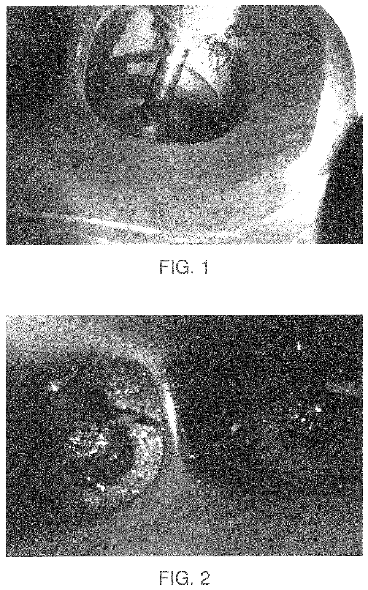
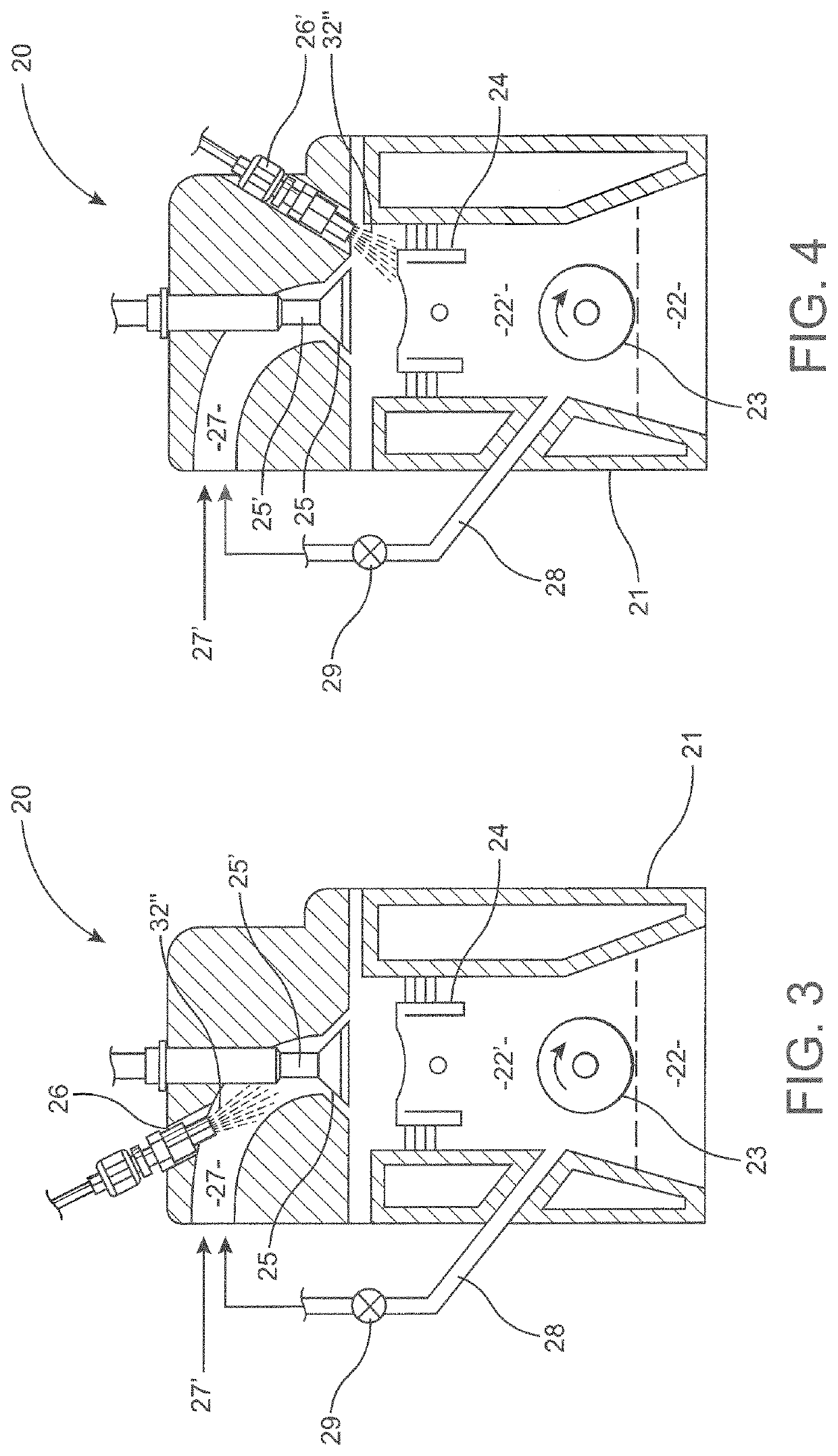
[0036]FIG. 1 is a photograph of a valve and valve stem in an internal combustion engine employing a direct fuel injection system after being driven approximately 15,000 miles. As is apparent, especially when compared to the photograph of the valve and valve stem in FIG. 2, relatively little carbon buildup is visible on either the valve or valve stem after 15,000 miles of operation.

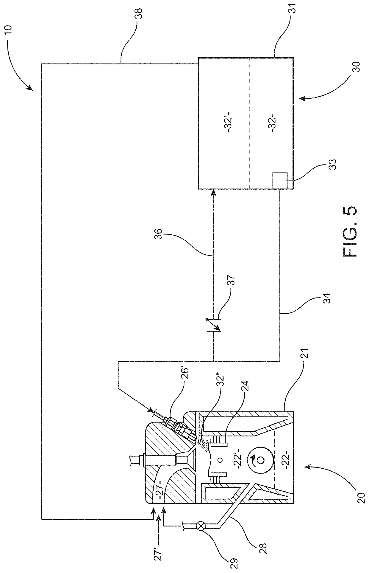
[0037]Conversely, the valve and valve stem in the photograph in FIG. 2, also of an internal combustion engine employing a direct fuel injection system but after being driven approximately 60,000 miles, show substantial visible amounts of carbon buildup on both the valve and valve stem. This visible carbon buildup is a result of engine oil which is entrained in oil laden positive crankcase ventilation (“PCV”) gases 22′, which are vented into an air intake manifold 27 of an internal combustion engine 20 having a direct fuel injector 26′, as shown best in FIG. 4.

[0038]FIG. 3 is a cross-sectional view of a por...


PUM


Abstract

A positive crankcase ventilation gas diversion and reclamation system comprises a positive crankcase ventilation gas diversion line to divert oil laden positive crankcase ventilation gases from the air intake manifold of an internal combustion engine. A positive crankcase ventilation gas diversion line directs oil laden positive crankcase ventilation gases into a vapor headspace of a fuel tank. A pressure sensor measures a vapor pressure in a vapor headspace of a fuel tank, and a fuel tank vent valve is operative with a fuel tank vent line. A controller actuates the fuel tank vent valve into an open position and discharges fuel enriched vapor to the air intake manifold of the internal combustion engine. A method permits diverting positive crankcase ventilation gasses from the air intake manifold of an engine, and reclaiming oil laden fuel components and / or particulates from positive crankcase ventilation gasses.

Description

BACKGROUND OF THE INVENTIONField of the Invention[0001]A positive crankcase ventilation gas diversion and reclamation system includes a positive crankcase ventilation gas diversion line to divert oil laden PCV gases from the air intake manifold of an internal combustion engine. The oil laden PCV gases are directed through an oil-vapor diffuser to at least partially separate crankcase oils from the PCV gases before the stripped gases are returned to the air intake manifold of the engine.Description of the Related Art[0002]In recent years, the number of Gas Direct Inject (“GDI”) engines provided by the automotive industry as an answer to improved fuel efficiency has increased dramatically, from approximately 5 million in 2009, to 50 million in 2016, and is projected to increase to 55 million by 2019. A total of 250 million vehicles were manufactured with GDI engines between model years 2009 and 2017. A significant and apparently unforeseen drawback to a GDI engine is the buildup of ca...

Claims


Application Information

Patent Timeline
Patent Type & Authority Patents(United States)
IPC IPC(8): F02M25/08F02M37/04F02M25/06F02M37/00F02M13/02F02D41/00F02D41/38F01M13/02F02D41/40
CPCF02M25/089F02M25/0872F02M37/0076F01M13/028F02M37/0023F02M25/0836F02M25/06F02D41/0045F02M37/04F02D41/38F02D41/401F02D2200/0602F02D2250/11F02D2250/08F02D2041/389
Inventor MESA, GILBERTO
Owner MESA GILBERTO
Why Eureka
Try Eureka