
Lubricant for preventing and removing carbon deposits in internal combustion engines

a technology for internal combustion engines and lubricants, which is applied in the direction of petroleum industry, lubricant compositions, base materials, etc., can solve the problems of hard carbon being the most difficult to remove, irreversible damage to the engine, and frequent carbon deposits, etc., to prevent and/or remove carbon buildup in internal combustion engines, prevent carbon buildup, and remove carbon buildup

Active Publication Date: 2021-08-03
VGP IPCO LLC
View PDF24 Cites 0 Cited by
  • Summary
  • Abstract
  • Description
  • Claims
  • Application Information

AI Technical Summary

Benefits of technology

The present invention is about a lubricant formulation that can prevent and remove carbon buildup in an engine. The formula is made up of a blend of base oils with specific properties such as a solvency test, volatility, oxidative stability, and viscosity. By using this blended oil, the formula effectively prevents carbon buildup and removes it from the engine. The base oil formulation is made by blending specific types of oil together to achieve the desired properties. This formula helps to keep the engine clean and running smoothly.

Problems solved by technology

Hard carbon is the most difficult to remove.
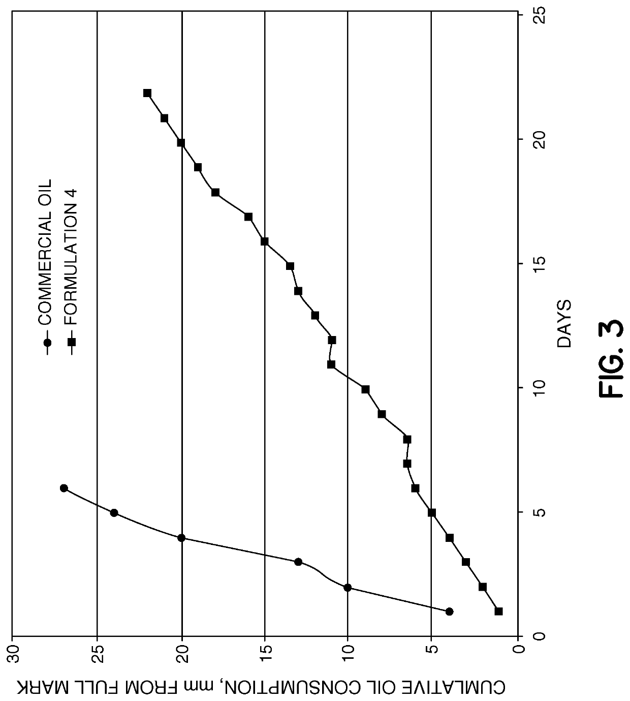
These carbon deposits frequently manifest themselves by increased oil consumption.
Carbon deposits between the rings and grooves and on the lands can cause irreversible damage to the engine.
Yet the ash containing components necessary to pass these demanding specifications typically exacerbate deposits.
Thus although it is possible to produce an engine oil with a low tendency to form deposits using conventional high aniline point base oils (e.g. some oils used in natural gas engines) it will typically not pass specifications for use with diesel engines.
Furthermore, such an oil outside the range of solvency proscribed herein does not have the effect of cleaning and freeing piston rings thereby reducing oil consumption or preventing loss of oil consumption.

Method used


Image

  • Lubricant for preventing and removing carbon deposits in internal combustion engines
  • Lubricant for preventing and removing carbon deposits in internal combustion engines
  • Lubricant for preventing and removing carbon deposits in internal combustion engines

Examples


Embodiment Construction

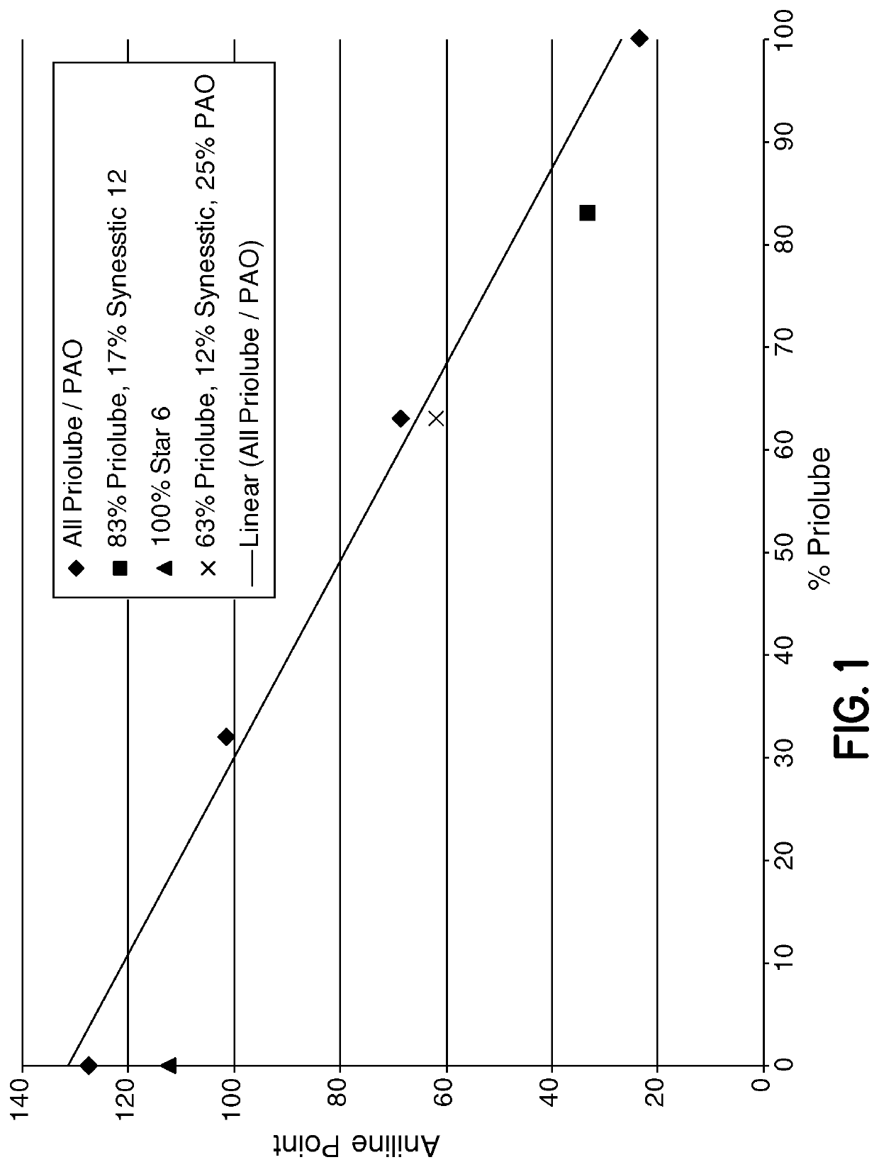
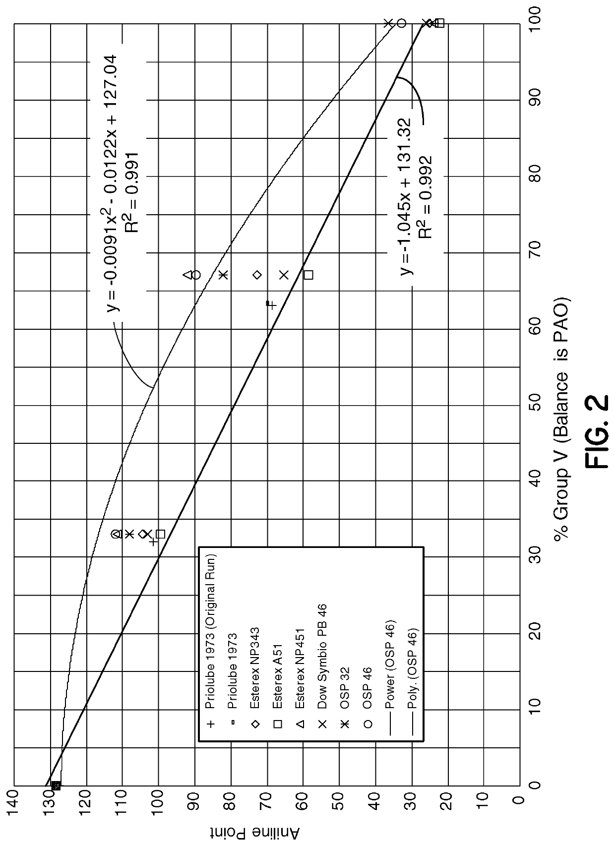
[0012]The lubricant of the present invention includes a base oil blend, which is a mixture of different base stocks in combination with typical additives normally found in lubricant formulations used for internal combustion engines. The base oil, which is a blend of two or more types of base oils, is blended together to establish a solvency which is adequate to control / remove the carbon deposits. In the present invention, solvency can be defined in various manners. One way of defining solvency is the aniline point. The aniline point is the minimum equilibrium solution temperature for equal volumes of aniline and a sample. In this case, the sample would be the base oil blend. It should be noted that when specifying the range of aniline point for the desired base oil blend it is understood that up to 25% of the formula may consist of other additives. Additives are frequently carried in up to 50% base oil. Thus, all base oil in the formulation, including base oil added with the additiv...


PUM

PropertyMeasurementUnit
viscosity indexaaaaaaaaaa
aniline pointaaaaaaaaaa

Abstract

A lubricant formulation which is effective to remove or prevent carbon deposits in internal combustion engines has a solvency as defined by aniline point from about 20 to about 115, a volatility (as measured by NOACK) of less than 15%, an oxidative stability (as measured by PDSC) of above 40 minutes and a base oil viscosity of above 2 and below 10 cSt. The lubricant formulation can be formed from a blend of Group III, IV and V lubricants, in particularly polyalphaolefins, alkylated naphthalenes and polar Group V base stocks such as polyol esters. The carbon deposits can be removed from the engine piston by simply running the engine with the lubricant for one required cycle, or can be used continuously in the engine to prevent buildup.

Description

PRIORITY CLAIM[0001]This application is a submission under 35 USC § 371 of International Application No. PCT / US2015 / 025,255, filed Apr. 10, 2015, which claims priority to U.S. Provisional Patent Application, Ser. No. 61 / 978,488, filed Apr. 11, 2014, both of which are incorporated herein by reference.BACKGROUND OF THE INVENTION[0002]There are three types of deposits which can form on pistons and rings: sludge, varnish and hard carbon. Hard carbon is the most difficult to remove. Over a period of time, carbon deposits can form in certain internal combustion engines, particularly on the piston lands, and in the grooves between the rings and the piston. These carbon deposits frequently manifest themselves by increased oil consumption. Carbon deposit can cause the piston rings to stick, which prevents them from forming a proper seal which allows oil into the combustion chamber and allows the combustion products into the oil. Carbon deposits between the rings and grooves and on the lands ...

Claims


Application Information

Patent Timeline
Patent Type & Authority Patents(United States)
IPC IPC(8): C10M111/00C10M111/04C10M169/04C10M111/02C10N30/02C10N30/04C10N30/10C10N30/12C10N30/18C10N30/00C10N40/25
CPCC10M111/04C10M111/02C10M169/04C10M2203/024C10M2203/1006C10M2203/1025C10M2203/1065C10M2205/0285C10M2205/223C10M2207/0406C10M2207/2805C10M2207/2825C10M2207/2835C10M2209/1023C10M2209/1033C10M2215/064C10M2227/061C10N2030/02C10N2030/04C10N2030/10C10N2030/12C10N2030/18C10N2030/52C10N2030/70C10N2030/74C10N2040/25C10M105/06C10M105/38C10M107/02C10M171/02C10N2020/02
Inventor YANG, YINGLOCKWOOD, FRANCES E.DOTSON, DANIEL J.FREDERICK, JOSHUADAASCH, JAMIE
Owner VGP IPCO LLC
Learn More