Cylinder bore wall heat insulation device, internal combustion engine, and automobile

a heat insulation device and cylinder bore technology, applied in the direction of engine cooling apparatus, cylinders, liquid cooling, etc., can solve the problems of fuel efficiency drop, achieve high adhesion, reduce thermal deformation amount, and improve the uniformity of a cylinder bore wall wall temperature

Active Publication Date: 2020-01-07
NICHIAS CORP
View PDF25 Cites 0 Cited by
  • Summary
  • Abstract
  • Description
  • Claims
  • Application Information

AI Technical Summary

Benefits of technology

[0018]According to the present invention, it is possible to provide a thermal insulator having high adhesion to a wall surface on a cylinder bore side of a groove-like cooling water channel. Therefore, according to the present invention, uniformity of a wall temperature of a cylinder bore wall is improved. It is possible to reduce a difference in a thermal deformation amount between an upper side and a lower side.

Problems solved by technology

This causes a decrease in fuel efficiency.

Method used


Image

  • Cylinder bore wall heat insulation device, internal combustion engine, and automobile
  • Cylinder bore wall heat insulation device, internal combustion engine, and automobile
  • Cylinder bore wall heat insulation device, internal combustion engine, and automobile

Examples


Embodiment Construction

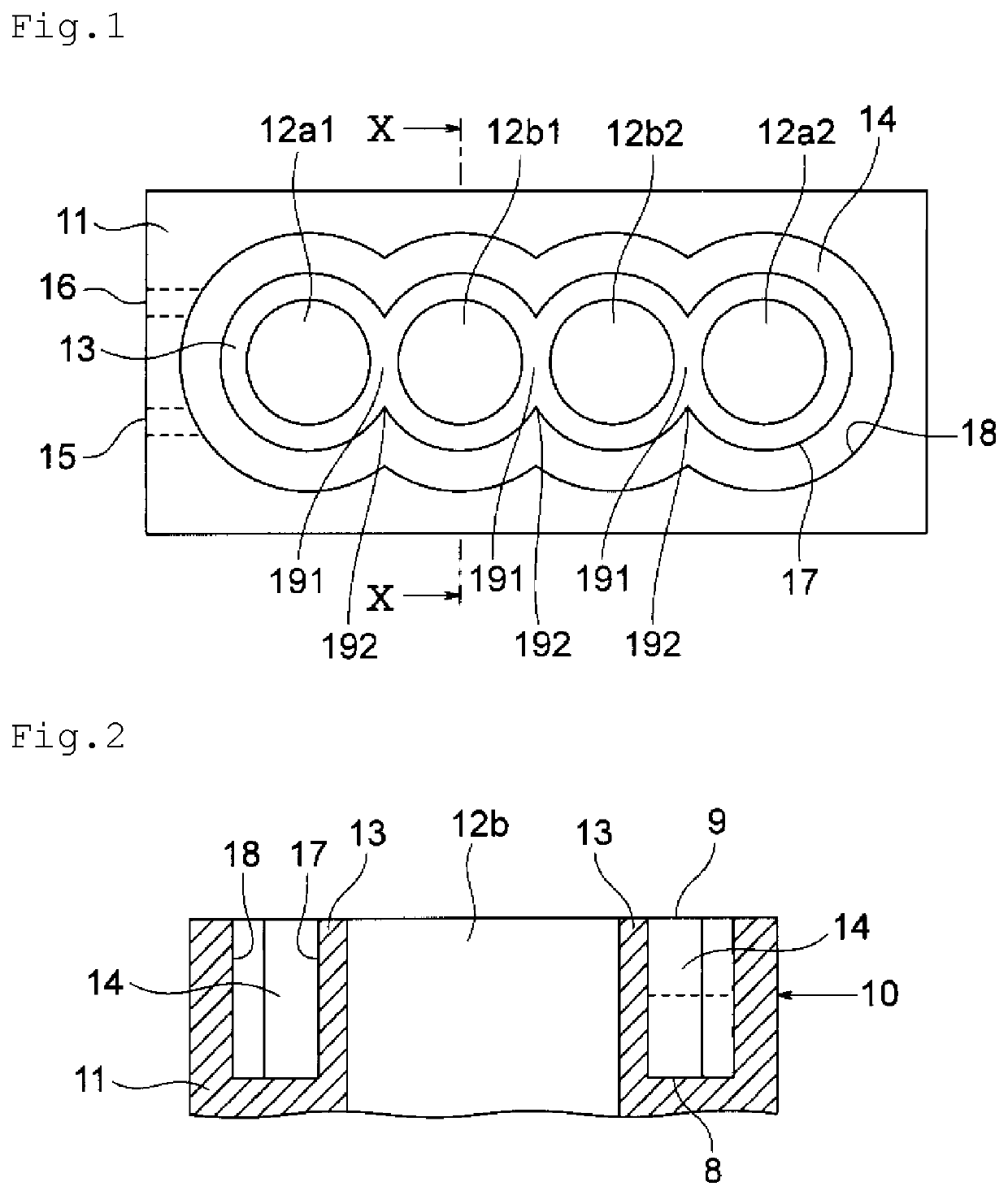
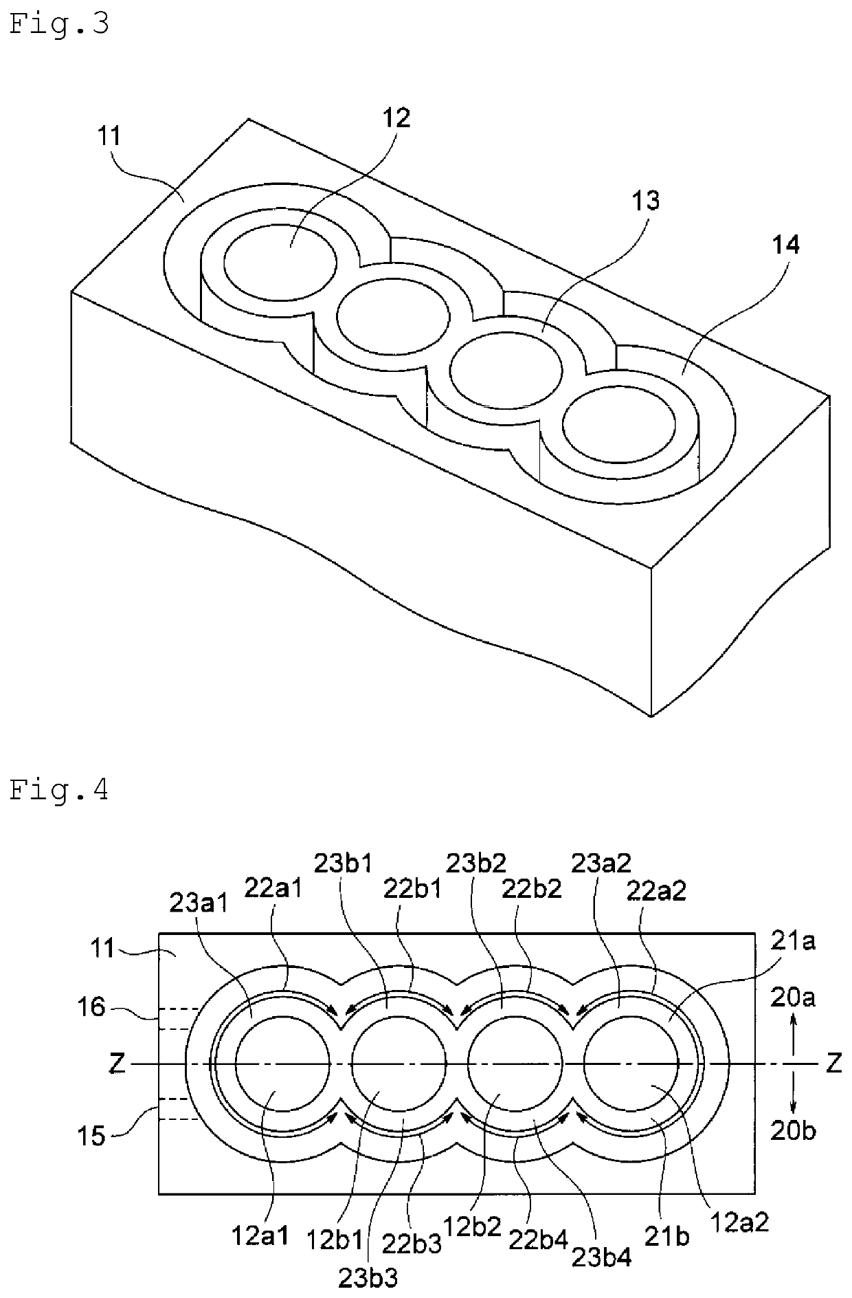
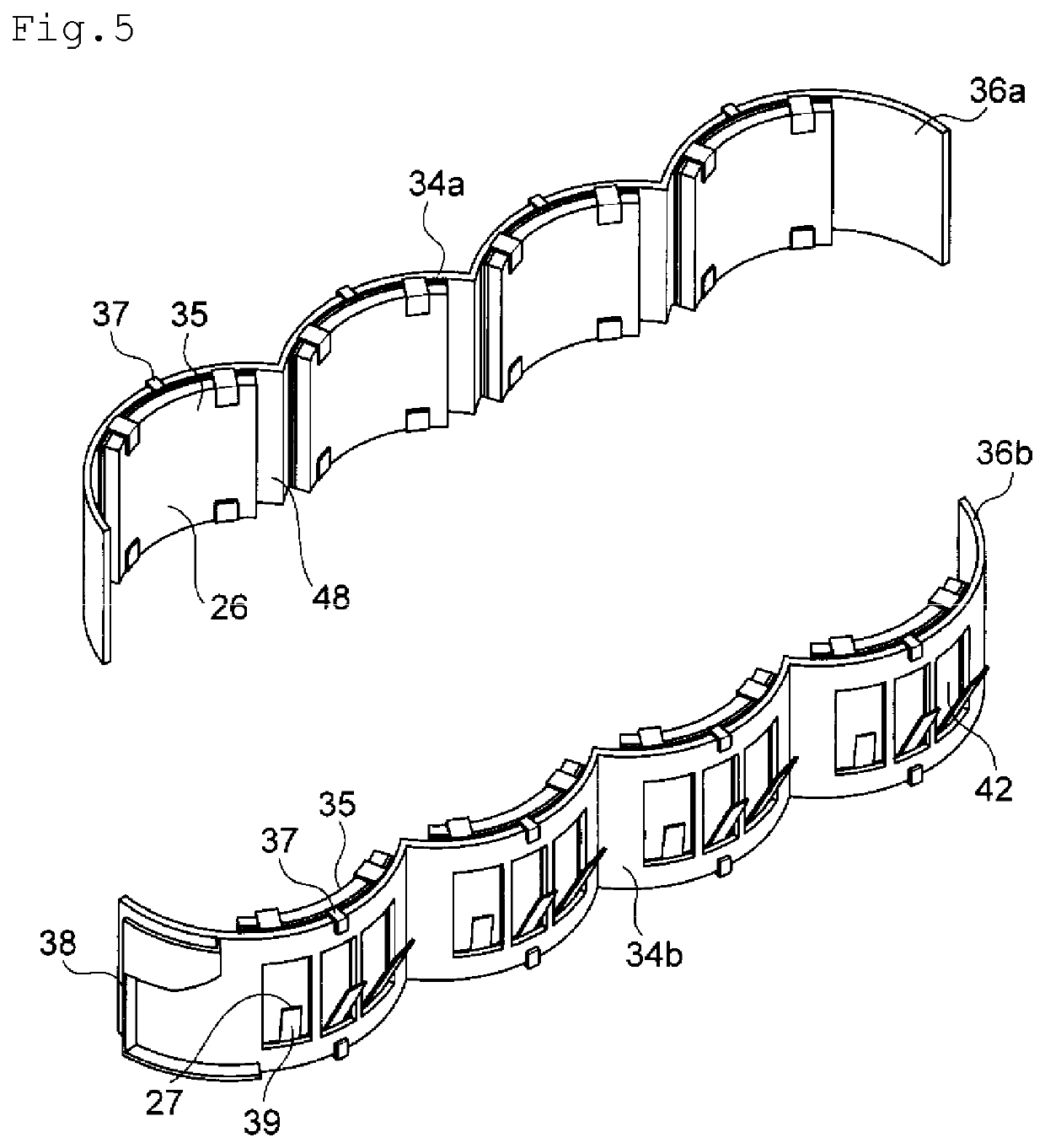
[0047]A cylinder bore wall thermal insulator of the present invention and an internal combustion engine of the present invention are explained with reference to FIG. 1 to FIG. 15. FIG. 1 to FIG. 4 show a form example of a cylinder block in which the cylinder bore wall thermal insulator of the present invention is set. FIG. 1 and FIG. 4 are a schematic plan view showing the cylinder block in which the cylinder bore wall thermal insulator of the present invention is set. FIG. 2 is an x-x line sectional view of FIG. 1. FIG. 3 is a perspective view of the cylinder block shown in FIG. 1. FIG. 5 is a schematic perspective view showing a form example of the cylinder bore wall thermal insulator of the present invention. FIG. 6 is a view of a thermal insulator 36a shown in FIG. 5 viewed from above. Note that, in FIG. 6, a insulating section at the right end among the bore wall insulating sections 35 fixed to the thermal insulator 36a is shown as being separated into each of the components. F...


PUM


Abstract

A cylinder bore wall thermal insulator set in a groove-like cooling water channel of a cylinder block of an internal combustion engine including cylinder bores and for insulating all bore walls of all the cylinder bores or a part of the bore walls of all the cylinder bores includes bore wall insulating sections having an arcuate shape when viewed from above and for insulating a wall surface on the cylinder bore side of the groove-like cooling water channel and a supporting section made of synthetic resin and having a shape conforming to a shape of the groove-like cooling water channel in a setting position of the thermal insulator, the bore wall insulating sections being fixed to the supporting section. The bore wall insulating sections include rubber members, rear surface pressing members, and elastic members.

Description

TECHNICAL FIELD[0001]The present invention relates to a thermal insulator disposed in contact with a wall surface on a groove-like cooling water channel of a cylinder bore wall of a cylinder block of an internal combustion engine, an internal combustion engine including the thermal insulator, and an automobile including the internal combustion engine.BACKGROUND ART[0002]In an internal combustion engine, the structure of which is such that an explosion of fuel occurs at a top dead point of a piston in a bore and the piston is pushed down by the explosion, temperature rises on an upper side of a cylinder bore wall and temperature falls on a lower side of the cylinder bore wall. Therefore, a difference occurs in a thermal deformation amount between the upper side and the lower side of the cylinder bore wall. Expansion is large on the upper side and, on the other hand, expansion is small on the lower side.[0003]As a result, frictional resistance between the piston and the cylinder bore ...

Claims


Application Information

Patent Timeline
Patent Type & Authority Patents(United States)
IPC IPC(8): F01P3/02F02F1/14
CPCF01P3/02F02F1/14F01P2003/021
Inventor FUJITA, YOSHIFUMIKATAOKA, TATSUNORI
Owner NICHIAS CORP
Why Eureka
Try Eureka