Resonant transformer with adjustable leakage inductance

a leakage inductance and resonant transformer technology, applied in the field of resonant transformers, can solve the problems of inability to adjust the leakage inductance from the inside and the efficiency of the resonant transformer cannot be enhanced,

Active Publication Date: 2020-01-07
YUJING TECH CO LTD
View PDF12 Cites 0 Cited by
  • Summary
  • Abstract
  • Description
  • Claims
  • Application Information

AI Technical Summary

Benefits of technology

[0008]Still another objective of the present invention is to provide a resonant transformer with adjustable leakage inductance that acts as a demagnetizing transformer at very low leakage inductance.

Problems solved by technology

Leakage inductance is generated as a result of the coupling coefficient between the primary winding and the secondary winding of the transformer being less than one, such that a portion of the winding does not effectively perform the transformation of an electrical energy, and the inductance produced by this portion of the winding is the leakage inductance.
However, in actual implementations, this is not possible.
Therefore, current resonant transformers typically use variable-frequency power supply as the power supply in order to adjust the value of ω, but Lk cannot be adjusted from the inside of the resonant transformer.
As a result, the efficiency of the resonant transformer cannot be enhanced.
However, such kind of resonant transformers are constrained by physical limits, such as their sizes and weights.
Therefore, under the constraints of a fixed volume, size or coil ratio, the leakage inductance cannot be adjusted at ease.
This fails to satisfy the different power requirements of various power supply systems.
Moreover, since manufacturers often need to create a variety of leakage inductances to satisfy the requirements of different power supply systems using the same structure, the range in which the leakage inductance can be adjusted is often limited, and circuit compromises are often made in existing transformers, and the performance of the resonant transformers cannot be efficiently improved.

Method used


Image

  • Resonant transformer with adjustable leakage inductance
  • Resonant transformer with adjustable leakage inductance
  • Resonant transformer with adjustable leakage inductance

Examples


Embodiment Construction

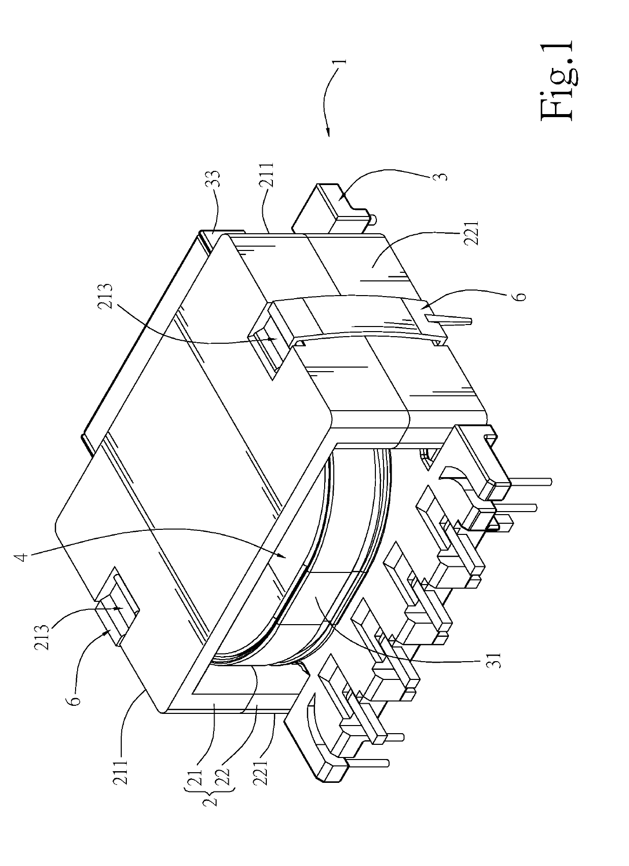
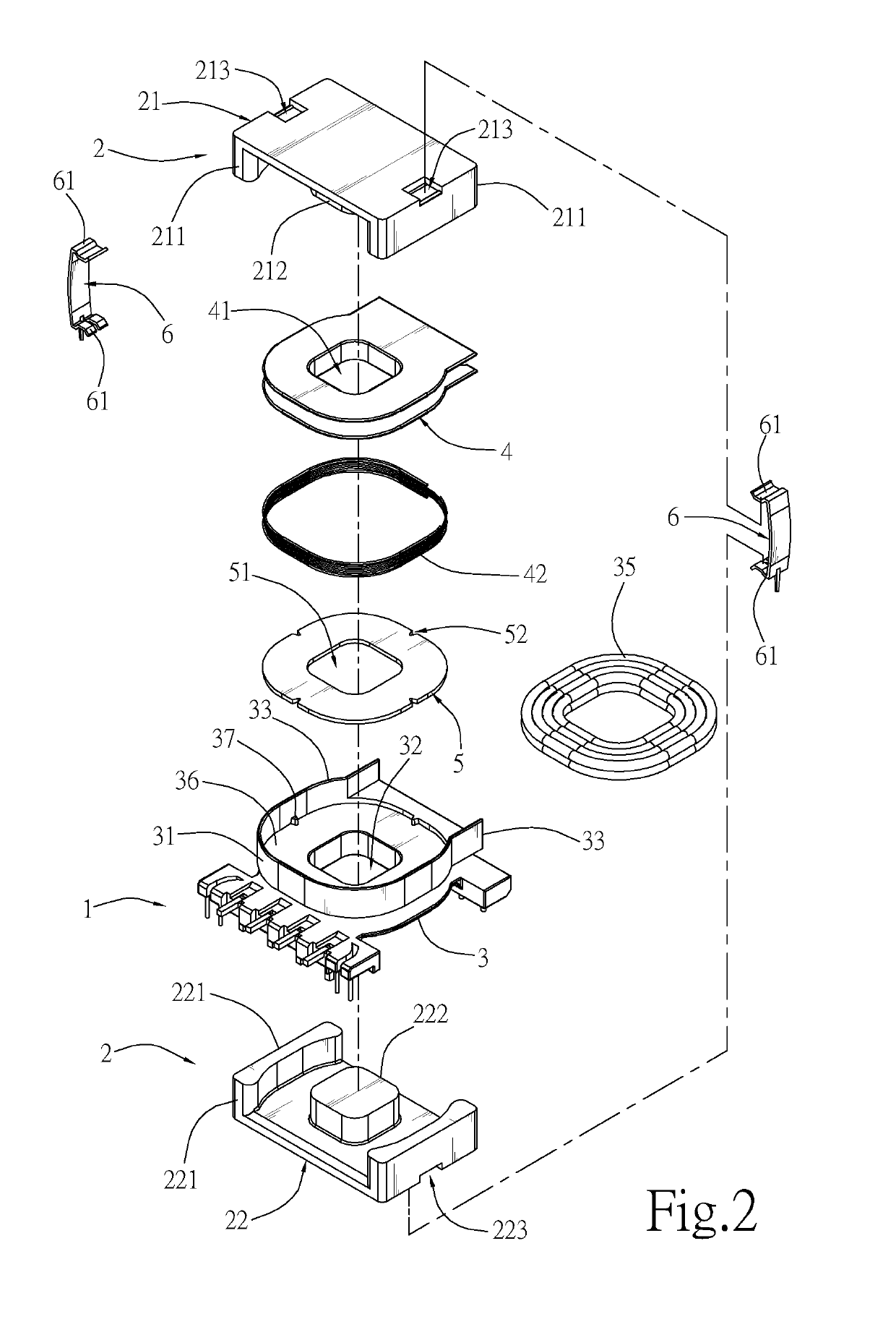
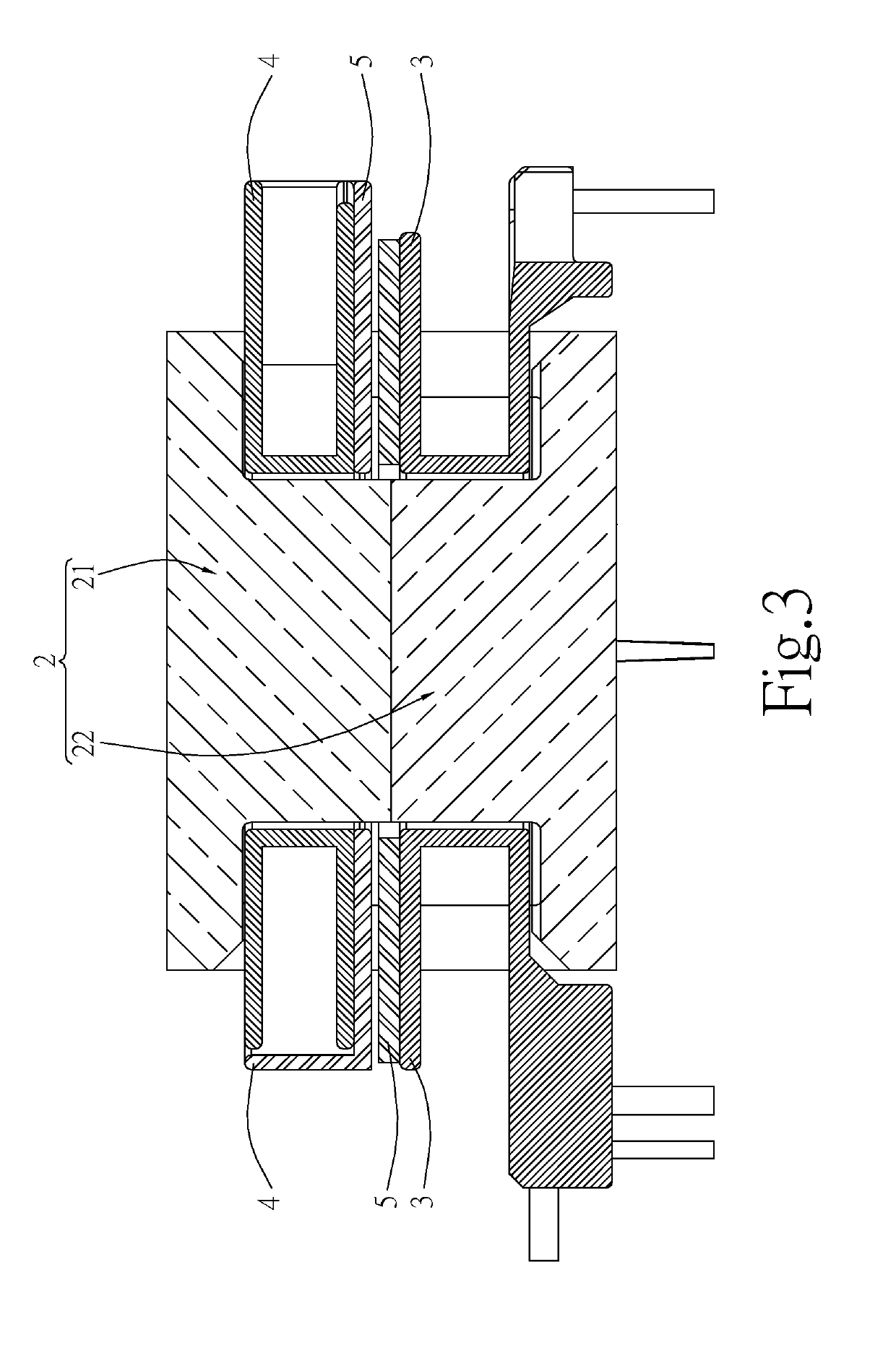
[0026]Referring to FIGS. 1-3, the structure of a resonant transformer 1 of the present invention essentially includes: a core group 2, a secondary winding group 3, a primary winding group 4, a magnetic sheet 5 and two clips 6.

[0027]The secondary winding group 3 includes a bobbin 31 having a first through hole 32. A wall plate 33 is provided around periphery of the top of the bobbin 31. A receiving space 36 is formed between the wall plate 33 and the top of the bobbin 31. A plurality of positioning columns 37 are provided at the bottom of the wall plate 33. A secondary coil 35 is wound inside the bobbin 31.

[0028]The primary winding group 4 includes a second through hole 41, which is in communication with the first through hole 32. A primary coil 42 is wound inside the primary winding group 4.

[0029]The magnetic sheet 5 includes a through hole 51, and a plurality of positioning notches 52 provided around the periphery of the magnetic sheet 5.

[0030]The core group 2 includes a first core...


PUM

PropertyMeasurementUnit
leakage inductanceaaaaaaaaaa
magneticaaaaaaaaaa
thicknessaaaaaaaaaa

Abstract

A resonant transformer with adjustable leakage inductance includes a secondary winding group, a primary winding group, a magnetic sheet and a core group. The primary winding group is provided on a bobbin of the secondary winding group, and the magnetic sheet is provided in the bobbin. The secondary winding group, the primary winding group and the magnetic sheet include a first through hole, a second through hole and a through hole, respectively. The core group includes a first core and a second core symmetrically disposed, which are disposed on top of and at the bottom of the primary winding group, respectively. During operation of the resonant transformer, the degree of coupling between the primary and secondary sides can be changed using the magnetic sheet. This allows the native leakage inductance to be altered to satisfy demands for various different resonant frequencies.

Description

BACKGROUND OF THE INVENTION1. Field of the Invention[0001]The invention relates to a resonant transformer, more particularly, a resonant transformer with adjustable leakage inductance and used as a demagnetizing transformer at very low leakage inductance.2. Description of the Prior Art[0002]In power supply systems for electronic products such as LCD TV, LLC architecture offering high efficiency and easy production has become increasingly popular. The use of the leakage inductance inherently brought by the main transformer in lieu of an external resonant inductor further simplifies the LLC architecture and has been widely adopted. The inherent leakage inductance of the integrated LLC transformer being used as a resonant inductor eliminates the need for an additional inductor component on the circuit, thereby reducing power consumption and improving efficiency. Moreover, zero voltage switching (ZVS) of the LLC architecture further reduces switching loss and noise.[0003]Leakage inducta...

Claims


Application Information

Patent Timeline
Patent Type & Authority Patents(United States)
IPC IPC(8): H01F27/30H01F13/00H01F27/32H01F38/08H01F27/245H01F38/10
CPCH01F38/10H01F13/006H01F38/08H01F27/325H01F27/245
Inventor YANG, SEN-TAI
Owner YUJING TECH CO LTD
Why Eureka
Try Eureka