Energy supply unit for transmitting auxiliary energy to an electrical device

a technology of auxiliary energy and energy supply unit, which is applied in the direction of electric variable regulation, process and machine control, instruments, etc., can solve the problems of inability to covert defects and inability to aging the insulation material by partial discharge, and achieve low leakage inductance, large coupling inductance, and simple and economical construction

Inactive Publication Date: 2007-05-22
GE POWER CONVERSION
View PDF11 Cites 2 Cited by
  • Summary
  • Abstract
  • Description
  • Claims
  • Application Information

AI Technical Summary

Benefits of technology

[0007]The present invention generally provides an energy supply unit that generates a low leakage inductance and a large coupling inductance and has a simple and economical construction.

Problems solved by technology

In this way, an aging of the insulation by partial discharges in the insulation material is not possible.
Moreover, the insulation section can be visibly configured so that covert defects are hardly possible.

Method used


Image

  • Energy supply unit for transmitting auxiliary energy to an electrical device
  • Energy supply unit for transmitting auxiliary energy to an electrical device
  • Energy supply unit for transmitting auxiliary energy to an electrical device

Examples


Embodiment Construction

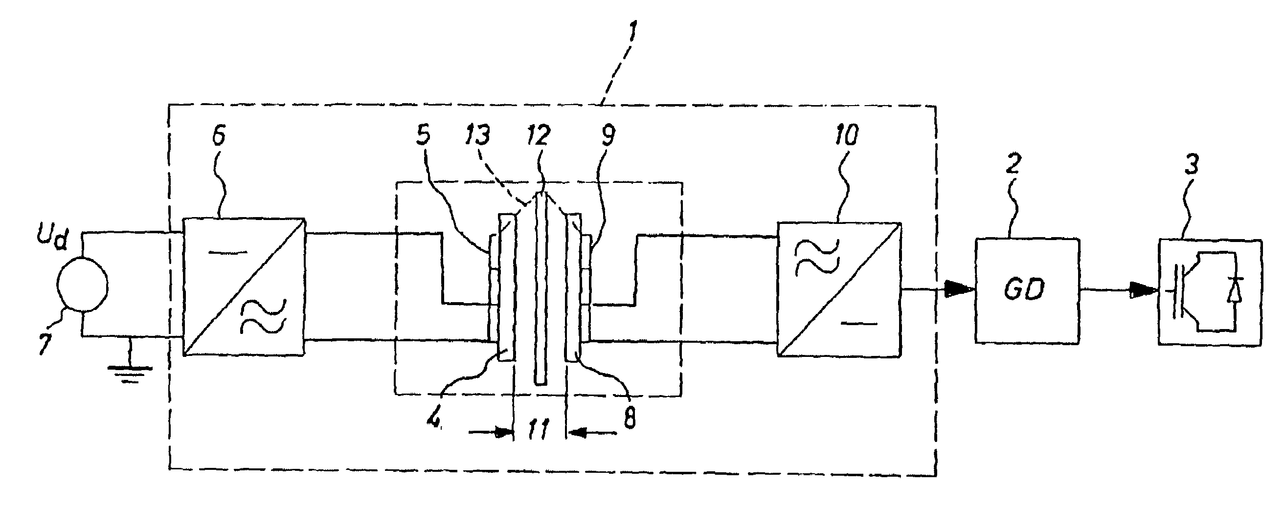
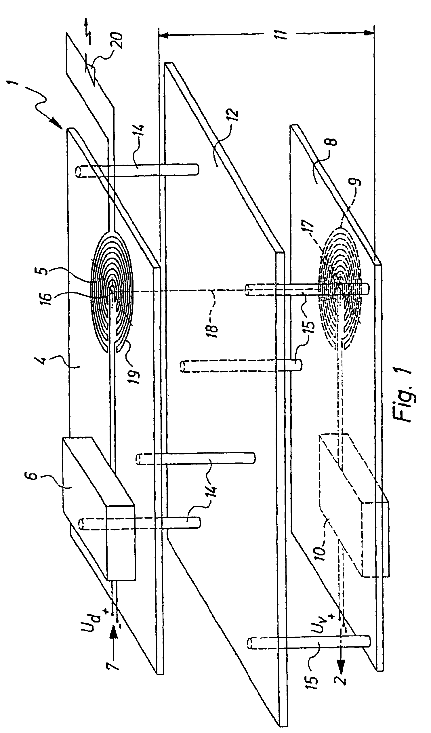
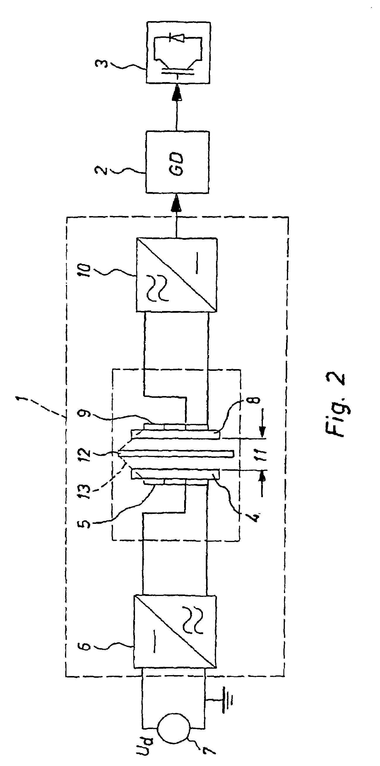
[0029]An energy supply unit of the invention is designated in entirely with the reference number 1 in FIG. 1 and FIG. 2. The energy supply unit 1 serves to transmit auxiliary energy for a control switch 2 (so-called gate drive, GD; cf. FIG. 2) in a power converter of a medium or high tension facility. The control circuit 2 serves to activate semiconductor power switches 3 of the power converter. The power converter is preferably constructed in multilevel switching. The control circuit 2 furnishes the power switches 3 with different, high potentials. The power circuits 3 are, for example, constructed as IGBT's (Insulate Gate Bipolar Transistors).

[0030]The energy supply unit 1 has a first supporting plate 4 with a primary coil 5 installed thereupon as a flat coil. The primary coil 5 is connected with a direct voltage source U_d through an oscillator circuit 6. The oscillator circuit 6 generates an alternating voltage for feeding the primary coil 5 on the basis of an input direct volta...


PUM

PropertyMeasurementUnit
frequencyaaaaaaaaaa
voltageaaaaaaaaaa
energyaaaaaaaaaa

Abstract

An energy supply unit includes a primary coil which is at least indirectly connected to an energy source. In a secondary coil which is at least indirectly connected to the control circuit, and an insulating section formed between the primary coil and the secondary coil. The auxiliary energy is transmitted via the insulating section by way of a magnetic alternating field. The energy supply unit further includes a first carrier plate, a primary coil embodied as a flat coil situated on the first carrier plate, a second carrier plate, and a secondary coil embodied as a flat coil situated on the second carrier plate. The insulating section is embodied as an interferric space formed between the primary coil and the secondary coil.

Description

[0001]This application is the national phase under 35 U.S.C. §371 of PCT International Application No. PCT / EP01 / 06325 which has an International filing date of Jun. 2, 2001, which designated the United States of America and which claims priority on German Patent Application number DE 100 39 707.7 filed Aug. 14, 2000, the entire contents of which are hereby incorporated herein by reference.FIELD OF THE INVENTION[0002]The present invention generally relates to an energy supply unit for transmitting auxiliary energy to an electrical device, especially for a control circuit in a medium or high tension facility. The energy supply unit may have a primary coil that stands at least indirectly in connection with an energy source, a secondary coil, that may stand at least indirectly in connection with the control circuit, and an insulating section that may be constructed between the primary coil and the secondary coil through which the transmission of the auxiliary energy takes place using a ...

Claims


Application Information

Patent Timeline
Patent Type & Authority Patents(United States)
IPC IPC(8): H01F27/42H01F37/00H01F38/00H01F27/28H02J5/00H02M3/28H05K1/16
CPCH01F27/2804H02J5/005H05K1/165H02J11/00H02J50/10
Inventor JAKOB, ROLANDRUDNISKI, DAVIDJUNGE, GUENTER
Owner GE POWER CONVERSION
Why Eureka
Try Eureka