Multiple output isolated power supply for automated test equipment and a method for providing multiple isolated output voltages

a technology of automated test equipment and isolated power supply, which is applied in the direction of electric variable regulation, process and machine control, instruments, etc., can solve the problems of increasing switching noise, increasing circuit area, increasing cost, etc., and achieves the effect of improving density, cost and noise (or signal-to-noise ratio)

Active Publication Date: 2020-08-27
ADVANTEST CORP
View PDF9 Cites 2 Cited by
  • Summary
  • Abstract
  • Description
  • Claims
  • Application Information

AI Technical Summary

Benefits of technology

This patent is about a low-profile, low-cost, and low-noise power supply that produces multiple isolated outputs for use in automated test equipment. This unique design uses a planar transformer which is low-profile, has good thermal characteristics, low leakage inductance, and is highly repeatable. Overall, this design is a more efficient and cost-effective alternative to traditional transformers.

Problems solved by technology

A use of these multiple DC-DC modules increases the area of the circuit, and / or increase the cost, and / or increases the switching noise and becomes a limitation of the channel density.
Accordingly, while in conventional solutions during the turn-off of the switches, a leakage inductance causes a large undesirable voltage spike and become radiated electromagnetic interference (EMI), by controlling switch voltage slew rate and switch current slew rates, undesired voltage spike can be reduced, resulting the DC / DC (converter) becoming a low noise (EMI) voltage supply.

Method used


Image

  • Multiple output isolated power supply for automated test equipment and a method for providing multiple isolated output voltages
  • Multiple output isolated power supply for automated test equipment and a method for providing multiple isolated output voltages
  • Multiple output isolated power supply for automated test equipment and a method for providing multiple isolated output voltages

Examples


Embodiment Construction

[0045]In the following, different inventive embodiments and aspects will be described. Also, further embodiments will be defined by the enclosed claims.

[0046]It should be noted that any embodiments as defined by the claims can be supplemented by any of the details (features and functionalities) described herein. Also, the embodiments described herein can be used individually, and can also optionally be supplemented by any of the details (features and functionalities) included in the claims.

[0047]Also, it should be noted that individual aspects described herein can be used individually or in combination. Thus, details can be added to each of said individual aspects without adding details to another one of said aspects.

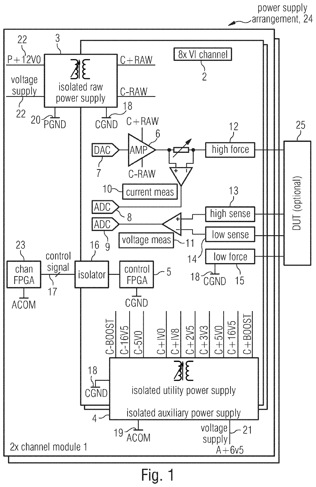
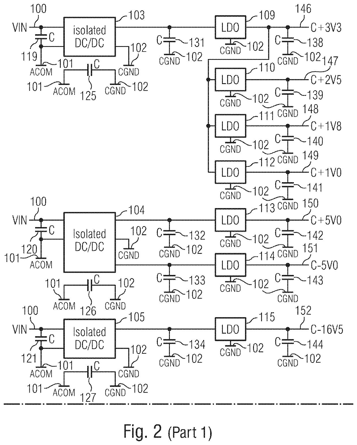
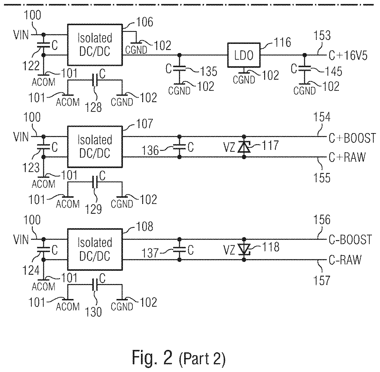
[0048]It should also be noted that the present disclosure describes, explicitly or implicitly, features usable in a multiple output isolated power supply, in a power supply arrangement and / or in an automatic test equipment. Thus, any of the features described herein can...


PUM

PropertyMeasurementUnit
poweraaaaaaaaaa
supply voltageaaaaaaaaaa
voltageaaaaaaaaaa

Abstract

A multiple output isolated power supply for the usage as a floating V / I source in an automated test equipment. The multiple output isolated power supply includes a multi-layer printed circuit board. Furthermore the multiple output isolated power supply includes a planar transformer, which includes a plurality of secondary windings associated with different output channels, arranged on or in the multi-layer PCB. At least two output channels out of the output channels of the multiple output isolated power supply includes a rectifier and a voltage regulator or a current regulator.

Description

CROSS-REFERENCES TO RELATED APPLICATIONS[0001]This application is a continuation of copending International Application No. PCT / EP2019 / 054918, filed Feb. 27, 2019, which is incorporated herein by reference in its entirety.BACKGROUND OF THE INVENTION[0002]Most of automatic test equipment (ATE) instruments are non-floating, and (or that means) its negative output terminal is connected to a system- or a common ground (GND), and the voltage potentials appear against GND. Instead (or by contrast) a floating V / I source, the voltage potential appears from positive terminal output to the negative terminal output. There is no conductive connection from either the positive terminal to GND or from negative output terminal to GND. So the floating V / I source operates like a battery.[0003]The necessity of an ATE floating V / I source is increasing in order to test next generation high power devices such as smart power, PMIC or automobile devices which have a high side switch in it. FIG. 8 illustrat...

Claims


Application Information

Patent Timeline
Patent Type & Authority Applications(United States)
IPC IPC(8): G01R31/28H01F27/28H01F27/24H02M3/335H05K1/14H02M1/00
CPCH01F2027/2819H05K1/144H01F27/2804H02M2001/0045H01F2027/2809G01R31/2834H02M1/00H02M3/335H01F27/24H02M3/33561H05K2201/09672H05K3/4644H05K1/165H05K2201/086H05K1/0262H02M1/0045H02M3/003
Inventor NAKAMURA, ATSUSHITHOMA, ANTON
Owner ADVANTEST CORP
Why Eureka
Try Eureka