Energy recycling and heat exchange systems

Active Publication Date: 2020-01-14
HURTADO ARTHUR FRANCISCO
View PDF12 Cites 2 Cited by
  • Summary
  • Abstract
  • Description
  • Claims
  • Application Information

AI Technical Summary

Benefits of technology

[0007]In another exemplary embodiment, the system to distill seawater with a condensing probe and recycled heat recycles the heat in the distillation process and reuses the heat to run the distillation process again, creating an energy loop. To help achieve this process, the condenser is placed within the evaporator so that the heat given off by the condenser is absorbed by the boiling seawater in the evaporator. This is particularly important, in that the latent heat of condensation is absorbed by the

Problems solved by technology

Moreover, this Summary is not intended for use as an aid in determining the scope of the claimed subject matte

Method used


Image

  • Energy recycling and heat exchange systems
  • Energy recycling and heat exchange systems
  • Energy recycling and heat exchange systems

Examples


Example

[0060]Example 1 is an illustration of a mechanical advantage system in which the fluid 351A, 351B is refrigerant R-410A and is being used in the expansive section 400B to drive the compressive section 400A to distill water. The boiler 360 contains a gas phase and liquid phase mixture of the refrigerant R-410 351A. Evaporator 425 contains seawater and condenser 410 contains condensed or the resultant distilled water 440. For the purpose of this illustration, it is assumed that seawater and pure water have the same boiling points.

[0061]The following example assumes a starting temperature in the evaporator 425 to be 212 F.° and that all of the heat is circulated back into the system 400.

Example 1

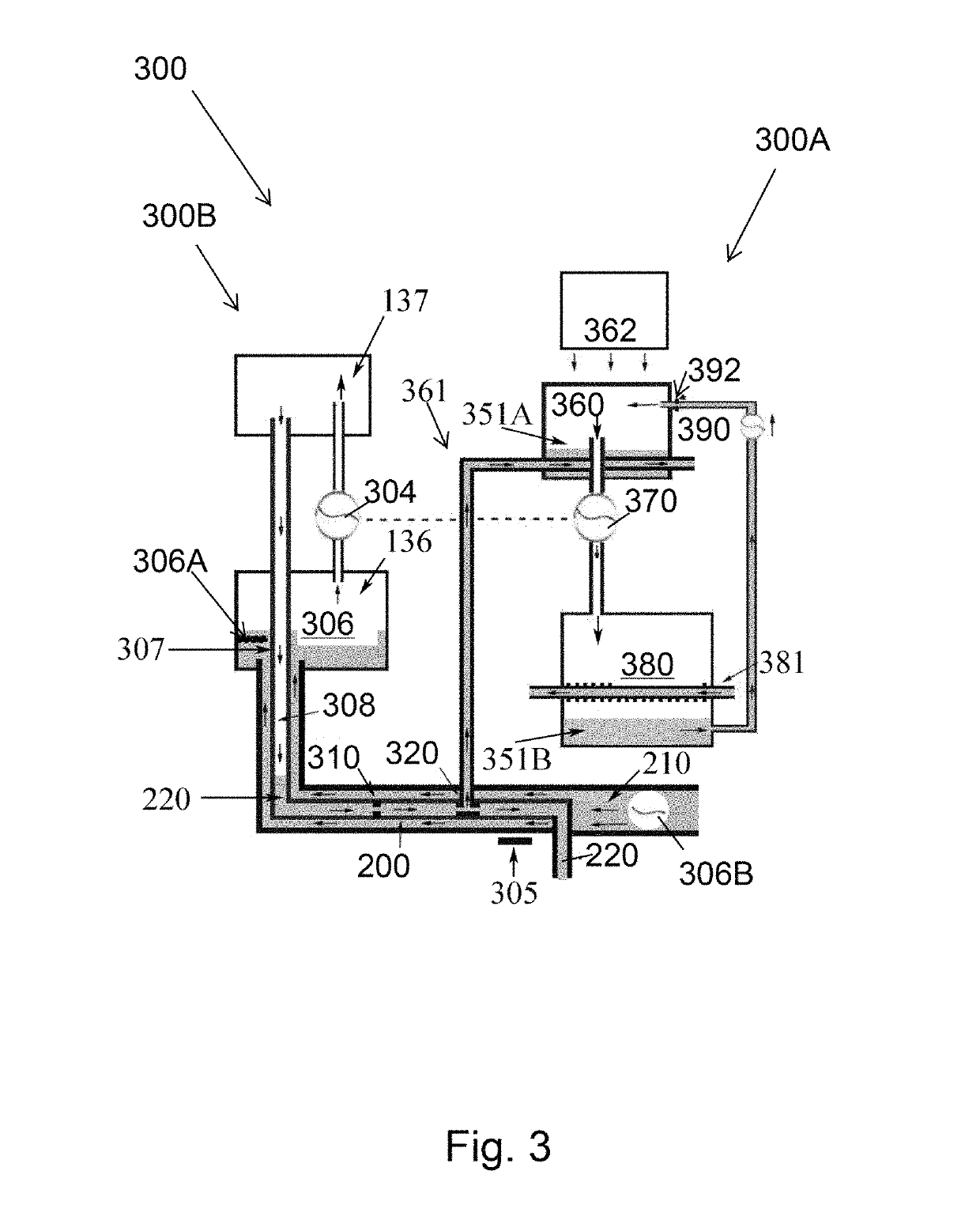
[0062]Chart 1 lists the parameters to be applied to the systems illustrated in FIG. 3 or FIG. 4.

[0063]CHART 1WaterCondenser 410:Temperature 222 F.°Pressure 18 PSI (denoted by P1)Evaporator 425:Temperature 212 F.°Pressure 14.69 PSI (denotedby P2)R-410ABoiler 360:Temperature 80 F.°Pressure 236 PS...

Example

[0087]Example 2 is an illustration showing a decrease in the level of mechanical advantage when water is utilized on the expansive section 400B, instead of R410A. Taking for example the parameters of chart 1 and instead of using R-410A on the expansive section 400B, R-410A is replaced with water. All temperature parameters remain the same as depicted in example 1 and listed in chart 1. However, both the compressive section 400A and the expansive section 400B of the system use water.

Example 2

Use of Water as the Refrigerant

[0088]Chart 2 lists the parameters to be applied in the system illustrated in FIG. 3 and FIG. 4.

[0089]CHART 2WaterCondenser 410Temperature 222° F.Pressure 18 PSI (denoted by P1)Evaporator 425Temperature 212° F.Pressure 14.69 PSI (denoted byP2)Boiler 360Temperature 80° F.Pressure .507 PSI (denoted by P3)Condenser 380Temperature 70° F.Pressure .363 PSI (denoted by P4)

[0090]Utilizing the parameters listed in Chart 1 and if A2=1 unit:

[0091]Note: A is the area that parti...

Example

[0099]Example 3 illustrates that distillation systems produce greater yields with increased temperature of the seawater 426 in evaporator 306 / 425. In this example the temperature of the seawater 426 in evaporator 425 is 281° F. and the temperature of the condenser 410 is 291° F. Chart 3 lists the parameters to be applied in the system illustrated in FIG. 3 and FIG. 4. The parameters for the expansive section 400B remain the same as those listed in chart 1. The parameters for the compressive section 400A have been increased. However, the condenser 410 and evaporator 425 on the compressive section 400A of both chart 1 and chart 3 have a temperature difference of 10° F.

[0100]CHART 3WaterCondenser 410Temperature 291° F.Pressure 58 PSI (denoted by P1)Evaporator 425Temperature 281° F.Pressure 50 PSI (denoted by P2)R-410AThe Boiler 360Temperature 80° F.Pressure 236 PSI (denoted by P3)Condenser 380Temperature 70° F.Pressure 201.5 PSI (denoted byP4)

[0101]Utilizing the parameters listed in Ch...


PUM


Abstract

A heat exchange system having at least one closed compartment containing in a first portion a first liquid having a first temperature at or near the first liquid's boiling point; a first thermally conductive conduit, containing a first fluid having a second temperature higher than the first temperature, submerged in the first liquid, causing at least a portion of the first liquid to absorb latent heat and boil within the at least one closed compartment, and convert to vapors; and a second thermally conductive conduit, containing a second fluid having a third temperature lower than the first temperature, passing through a second portion of the at least one closed compartment where the vapors contact the second thermally conductive conduit containing the second fluid, causing the vapors to lose latent heat and condense, and join the first liquid in the first portion of the at least one closed compartment.

Description

CROSS-REFERENCE TO RELATED APPLICATIONS[0001]This application claims priority to U.S. Non-Provisional application Ser. No. 14 / 562,617 filed on Dec. 5, 2014, which claims priority to U.S. Provisional Application No. 61 / 963,472 filed on Dec. 6, 2013, U.S. Provisional Application No. 61 / 995,308 filed on Apr. 8, 2014, and U.S. Provisional Application No. 62 / 071,542 filed on Sep. 29, 2014; and this application also claims priority to U.S. Non-Provisional application Ser. No. 14 / 048,523 filed on Oct. 8, 2013, which claims priority to U.S. Provisional Application No. 61 / 795,143 filed on Oct. 12, 2012 and U.S. Provisional Application No. 62 / 282,623 filed on Aug. 7, 2015, and the respective disclosures are incorporated herein by reference to the extent that they do not conflict with the present application.BACKGROUND OF THE INVENTION1. Field of the Invention[0002]The present invention relates generally to distillation systems and methods, and particularly to a low cost, energy-saving method ...

Claims


Application Information

Patent Timeline
IPC IPC(8): C02F1/04F25B27/00B01D3/00F25B11/02F25B7/00C02F103/08
CPCB01D3/007C02F1/041F25B27/005F25B7/00F25B11/02C02F2103/08B01D1/26B01D1/28B01D1/2843B01D1/2846
Inventor HURTADO, ARTHUR FRANCISCO
Owner HURTADO ARTHUR FRANCISCO
Why Eureka
Try Eureka