Multi-function tool, kit, and methods of using the same
a multi-functional, tool technology, applied in the direction of semiconductor devices for light sources, lighting and heating devices, lighting support devices, etc., can solve the problems of material and manufacturing costs, increased size, weight and volume, and limited clipping to thin materials such as cloth, so as to achieve economic cost of production
- Summary
- Abstract
- Description
- Claims
- Application Information
AI Technical Summary
Benefits of technology
Problems solved by technology
Method used
Image
Examples
embodiment 1
B. Embodiment 1
[0087]1. Apparatus
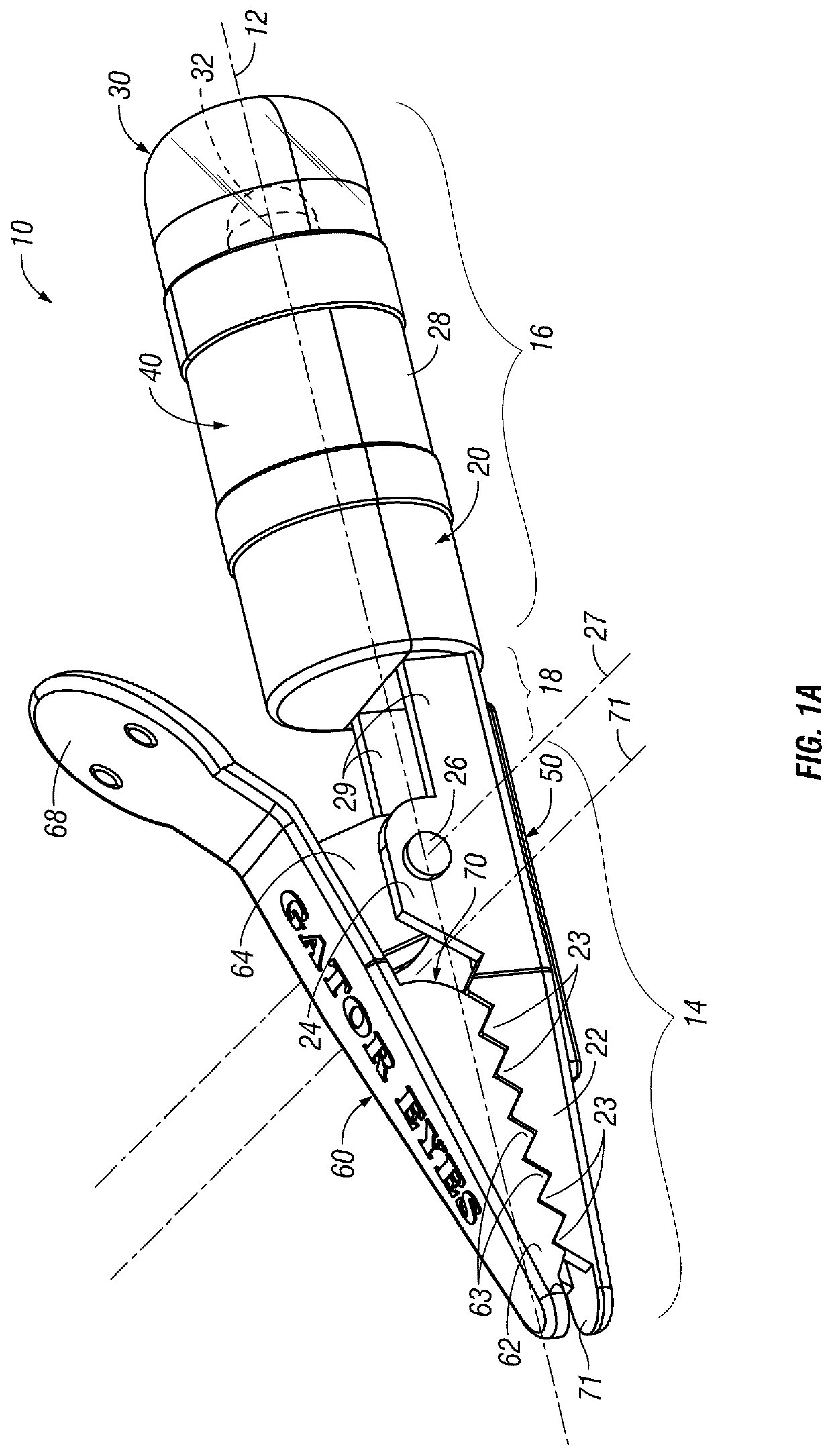
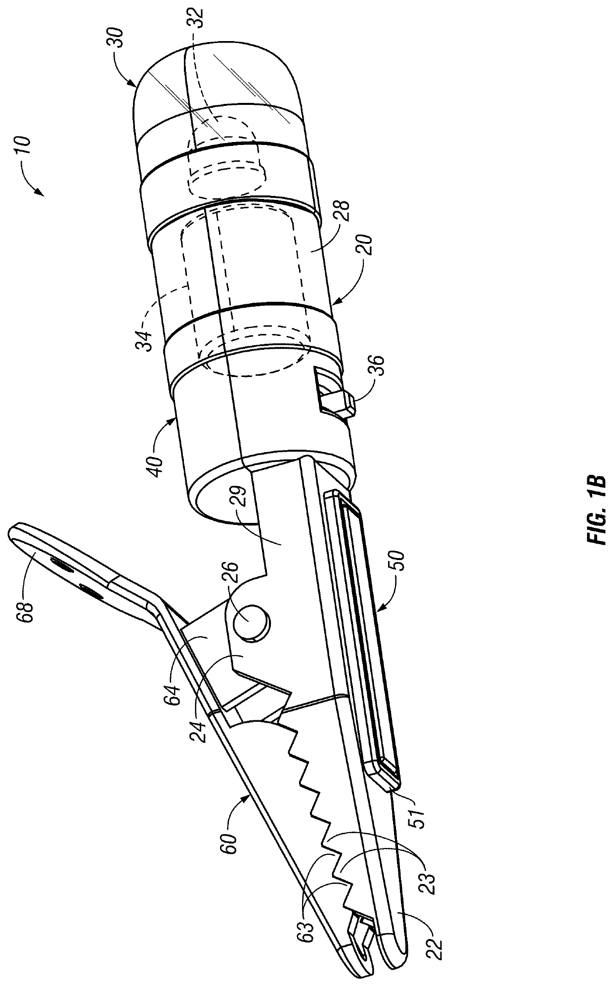
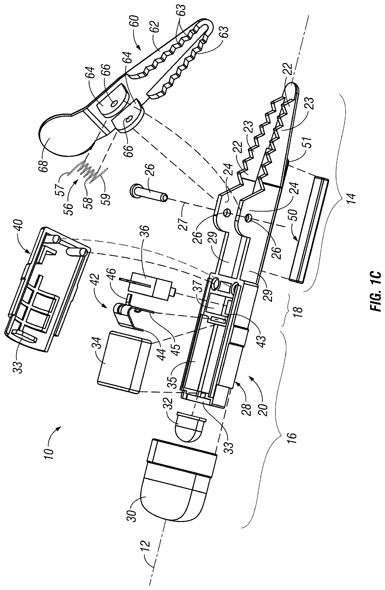
[0088]With specific reference to FIGS. 1A-H to FIGS. 2-10L, a first embodiment of a mini-light assembly 10 includes an integrated combination with multiple potential purposes and functions. Assembly 10 has a general longitudinal axis 12. It is to be understood that this is but one embodiment according to the invention. It has multiple functions and uses. Other embodiments can include a subset of those functions in different combination.
[0089]A first end 16 of assembly or tool 10 includes a cylindrical housing portion associated with an LED light source 32 and circuit to operate it to provide a mini-light functionality for such things as task and fiducial marking.
[0090]A second end 14 of assembly 10 includes both a clamp or clip, a retaining gap behind the clip, and a magnetic mount 50 all to provide a variety of mounting / retaining functions.
[0091]A transition section 18 links and supports ends 14 and 16.
[0092]In this embodiment, the body of tool 10 i...
second exemplary embodiment
C. Second Exemplary Embodiment
[0167]FIGS. 11A-D through 24C illustrate another exemplary embodiment 10′ according to the invention. As will be appreciated, many of its functionalities are similar to the first exemplary embodiment discussed earlier. Significant differences are as follows.
[0168]As can be seen, a first distal section of clip 14′ has a linear section of mating teeth 23′ and 63′. An open area or gap 70′ is intermediate that linear abutting tooth section and pivot pin 26′. The main difference is that this opening or gap 70′ also has serrations or teeth 72′ formed on movable jaw 62′ and the fixed jaw 22′ essentially all around that opening. This adds an additional gripability feature, if this gap area 70′ is used to grip an object or objects with clamping force, but it also can help a retaining function.
[0169]Further, opening 70′ is substantially bigger than gap 70 of the first embodiment and has the following features. First, a substantially oblong shape between planes P1...
third exemplary embodiment
D. Third Exemplary Embodiment
[0177]By reference to FIGS. 25A and B another embodiment according to aspects of the invention is illustrated. This embodiment 10″ includes basically just the end 14 or 14′ of embodiments one and two. As such, it includes a base 20″ that includes a bottom jaw 22″. A separate moveable jaw 60″ with jaw portion 62″ is pivotally attached at one set of adjacent aligned ends of jaws 22″ and 62″. The pivot connection can be like that of embodiments one or two.
[0178]A gap 70″ is between meshing teeth 23″ / 63″ at the other adjacent ends of jaws 22″ and 62″. In FIGS. 25A and B it is similar to gap 70′ but could take a variety of forms. The multi-functions of clamping action and retaining action as discussed with Embodiments One and Two are thus embodied in assembly 10″.
[0179]In one variation to assembly 10″, a magnet 50″ (like magnet 50 or 50′) could be built into base 20″.
E. Options and Alternatives
[0180]The foregoing first and second embodiments are but a few spe...
PUM
 Abstract
Description
Claims
Application Information
 - R&D
- Intellectual Property
- Life Sciences
- Materials
- Tech Scout
- Unparalleled Data Quality
- Higher Quality Content
- 60% Fewer Hallucinations
Browse by: Latest US Patents, China's latest patents, Technical Efficacy Thesaurus, Application Domain, Technology Topic, Popular Technical Reports.
© 2025 PatSnap. All rights reserved.Legal|Privacy policy|Modern Slavery Act Transparency Statement|Sitemap|About US| Contact US: help@patsnap.com


