Method for the characterization of objects

a technology for characterization and objects, applied in the field of characterization of objects, can solve problems such as difficult and reliable detection of similar, but not exactly identical objects

Active Publication Date: 2020-01-14
PHENOSPEX
View PDF14 Cites 0 Cited by
  • Summary
  • Abstract
  • Description
  • Claims
  • Application Information

AI Technical Summary

Benefits of technology

[0007]In a method for characterizing an object by means of distance measurement, elevation profiles are determined in particular in a line-wise manner by distance measurement. In this regard, the distance measurement may e.g. be a known method for distance measurement. The determined elevation profiles are subsequently evaluated for characterizing the object. The characterization of the object includes the position and / or at least one object-specific parameter of the object. The position of the object e.g. allows for a sorting or subsequent treatment, in particular for a harvesting. The object-specific parameter allows the object to be assessed, e.g. by a condition assessment regarding the growth, ripeness, appearance and / or the like, wherein the assessment is a quantified assessment. In addition, the object-specific parameter e.g. allows to provide a treatment and / or sorting dependent on the parameter. Therefore, for a subsequent quality check, the characterization of the object may not be based only on the elevation information about the object, but it is possible to take into account the position and / or at least one object-specific parameter for that purpose.
[0012]This method is also known as tessellation, wherein, when triangles are used, exactly two triangles are determined from two data points of a first elevation profile and two data points of a second elevation profile. Thereafter, a normal vector is determined for each of these surfaces, starting from the surface element. Therefore, the number of surface elements and normal vectors is identical. Specifically, the normal vector defines a direction, as well as an origin starting from the surface element. The normal vector has no predetermined length. Thus, the normal vector may alternatively also be conceived as a straight line intersecting with the surface element and extending in a direction perpendicular to the surface element. As an alternative, the normal vector may be conceived mathematically as a half-line starting from the surface element in a direction perpendicular to the surface element. In both cases, the length of the straight line and the half-line is not defined and in particular not limited. Here, the direction of the normal vectors may be defined such that, with concave objects, it is oriented towards the distance measuring device and that, with convex objects, it is directed away from the distance measuring device. The point of intersection of the normal vectors is determined as the position of the object. As an alternative, the point of the highest intersection density is determined as the position of the object, in particular if not only a single point of intersection exists, which is true only in the special case that the object is a sphere. As an alternative, the position mean value or the center of gravity of all points of intersection of the normal vectors is determined as the position of the object. For this purpose, the points of intersection of the normal vectors may first be projected on a plane and the position of the object on this plane may be determined from the point of intersection or the point with the highest intersection density or from the mean value or the center of gravity of all points of intersection. The plane is in particular a plane that is parallel to the plane in which the objects are arranged, preferably a horizontal plane. Thus, the position of the object is reliably determined. In particular, for objects that are similar in shape, yet not exactly identical, such as e.g. plants or harvest products, it is possible to exactly determine the position individually for each single object in a simple manner from the detected elevation profiles.
[0014]Preferably, a region B having an area A is determined, within which the object is essentially located. Here, the region B may be determined empirically or it may be calculated, e.g. by the distance between two objects. The region B may be predefined or determined individually for an object or it may be chosen or determined in an identical manner for a plurality of objects. Thereafter, the maximum length of the normal vectors is limited to a region B′ with the area C12·A, where the region B′ is arranged symmetrically around the respective origin of the normal vector. Here, C1 is in particular chosen to be greater than 1. C1 may be predefined by the user, e.g. empirically predetermined, or it may be adjusted in the course of the process so that an optimum result is obtained. Due to the limitation of the maximum length, the calculation process for the points of intersection of the respective normal vectors is reduced. Thereby, the computing effort for the determination of the position of an object is maintained low and the execution of the process is accelerated.
[0016]Preferably, a region B having an area A is determined, within which the object is essentially located. The region B may be the same region as described above. The minimum length of the normal vectors is then limited to a region B″ having the area C22·A, where the region B″ is arranged symmetrically around the origin of the respective normal vector. Here, C2 is in particular chosen to be less than 1. A limitation of the minimum length of the normal vectors takes into account that, immediately originating from the surface element, no point of intersection with another normal vector must be assumed. Thereby, the computing effort for the determination of the position of an object is reduced and the execution of the process is accelerated. For this purpose, C2 may be empirically predetermined, or it may be determined from the current process and be adjusted.
[0025]In another embodiment of the method, the elevation profiles determined are evaluated in real time or at least essentially in real time for a characterization of an object. Thus, the characterization of the object is immediately available so that the object can be assessed, sorted and / or processed further based on the characterization, without the characterization causing a delay in the process.
[0026]In another embodiment of the method, a characterization is performed as soon as a further line-wise elevation profile has been determined. Thus, it is not necessary to wait until all elevation profiles for an object are detected by the distance measurement so that the computational effort can be distributed over the duration of the entire distance measurement, i.e. all line-wise elevation profiles. In another embodiment distance measurement is performed using a sensor, wherein in particular a source and a camera are arranged within the sensor. Here, the object is moved relative to the sensor by moving the object and / or by moving the sensor. Thus, due to the relative movement of the object to the sensor, it is possible to successively determine one line-wise profile after the other, so as to capture the entire object. With a uniform movement, it is possible e.g. to select a time interval for the respective detection of a new elevation profile. The uniform movement ensures that distance between the elevation profiles is substantially constant. As an alternative, the distance traveled may be detected and a new line-wise elevation profile can be generated at a predetermined distance from the last elevation profile. As an alternative, the generation of a new elevation profile may be initiated by a trigger input to the sensor caused by a predetermined event such as e.g. the advance of a conveyor belt or the like. Thereby, it is ensured that a sufficient number of line-wise elevation profiles are determined and that the distance between them is uniform or constant.

Problems solved by technology

However, reliable detection is difficult with similar, but not exactly identical objects, where e.g. each object has an individual shape, as is the case with plants, harvest products or animals.

Method used


Image

  • Method for the characterization of objects
  • Method for the characterization of objects
  • Method for the characterization of objects

Examples


Embodiment Construction

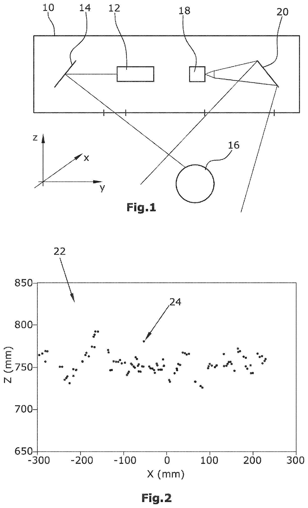
[0040]In a method for characterizing an object by means of distance measurement, line-wise elevation profiles are first determined by means of distance measurement and then evaluated in a suitable manner for the characterization of the object, wherein the characterization of the object includes the position and / or at least one object-specific parameter of the object. In this context, a laser triangulation system as illustrated in FIG. 1 can be used for distance measurement. The system comprises a sensor 10 in which a line laser 12 is arranged which illuminates an object 16 via a mirror 14. Via a further mirror 20, the line generated by the laser 12 on the object 16 is imaged by a camera 18 which is also arranged in the sensor 10. The line on the object 16 is distorted by the topology of the object 16. Based on this distortion, an evaluation means which is connected to the camera, can determine an elevation profile along the line generated by the laser 12. Thereby, according to the c...


PUM


Abstract

A method for characterizing an object using distance measurement includes: determining elevation profiles using distance measurement, and evaluating the determined elevation profiles for a characterization of the object, the characterization includes a position and / or at least one object-specific parameter of the object.

Description

CROSS-REFERENCE TO RELATED APPLICATION[0001]This application claims priority to European Patent Application No. 17158433.7 filed Feb. 28, 2017, the disclosure of which is hereby incorporated in its entirety by reference.BACKGROUND OF THE INVENTION[0002]Non-limiting embodiments or aspects of the present invention relate to a method for characterizing an object using distance measurement.[0003]In some distance measurement methods, an object is illuminated in a line-shaped manner using ultrasound or light. Here, ultrasound and light are generated by a source. In some laser triangulation methods, this is a line laser. Due to the topography of the object, the line is distorted. A camera captures the line distortion and uses the same to determine an elevation profile along the illuminated line. Here, the camera and the source are typically combined to a sensor. For capturing the entire surface of an object, either the sensor is moved relative to the object or the object is moved e.g. by a...

Claims


Application Information

Patent Timeline
Patent Type & Authority Patents(United States)
IPC IPC(8): G01B11/25G01S7/48G01S7/52G01S17/48G01S15/08
CPCG01S7/52017G01S17/48G01S7/4808G01S15/08G06T7/521
Inventor ZHOKHAVETS, ULADZIMIRHUMMEL, GRÉGOIRE MARTINSCHWARTZ, STEFAN
Owner PHENOSPEX
Why Eureka
Try Eureka