Resistance method

a resistance method and resistance technology, applied in the field of resistance methods, can solve the problems that no such method has been used with the intent of doing work, and achieve the effects of increasing or decreasing the electrical resistance encountered, increasing resistance, and increasing the conductivity

Active Publication Date: 2020-01-14
COBB JR JOHN ARTHUR
View PDF11 Cites 0 Cited by
  • Summary
  • Abstract
  • Description
  • Claims
  • Application Information

AI Technical Summary

Benefits of technology

[0013]The aforesaid and other objectives are realized by providing a system and method of manipulating the resistance of a given substance or solution as experienced by an electrical current with a resistance system and method with the goal of harvesting the results of the higher or lower electrical resistance. The method includes wiring one or more insulated hydrolysis reactors together in series, each reactor including a cathode and anode oriented to produce a spark gap. A computer control system monitors variables such as temperature, reactor pressure, salinity, and current amperage, and further includes output accessories to alter these variables as may be desirable. By increasing or decreasing the electrical resistance encountered by the electrical current within the reactor, increased resistance within the reactor substance (typically water) may be heated and even produce steam, which in turn can be harvested to do work. If resistance is lowered, the electrical current may pass more efficiently through the reactor substance or solution, creating a higher level of conductivity. The steps of the instant method are designed to increase the overall efficiency of the aforementioned process.

Problems solved by technology

While the general electrical principles of resistance, conductivity, and heat production are known in the art, there has heretofore never been an articulated method of manipulating the factors than impact the resistance impacting an electrical current, and specifically, no such method has been utilized with the intent to do work, for example the creating of hot water or steam within a closed system.

Method used


Image

  • Resistance method
  • Resistance method
  • Resistance method

Examples


Embodiment Construction

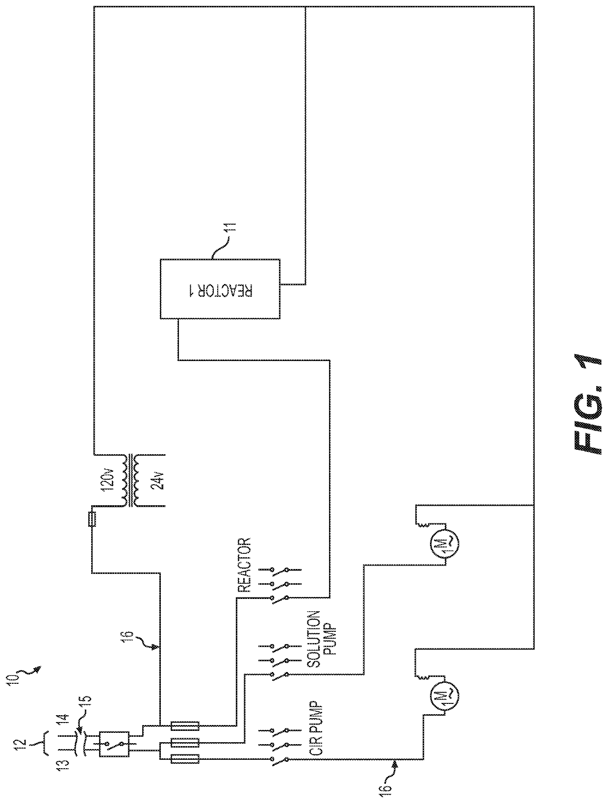
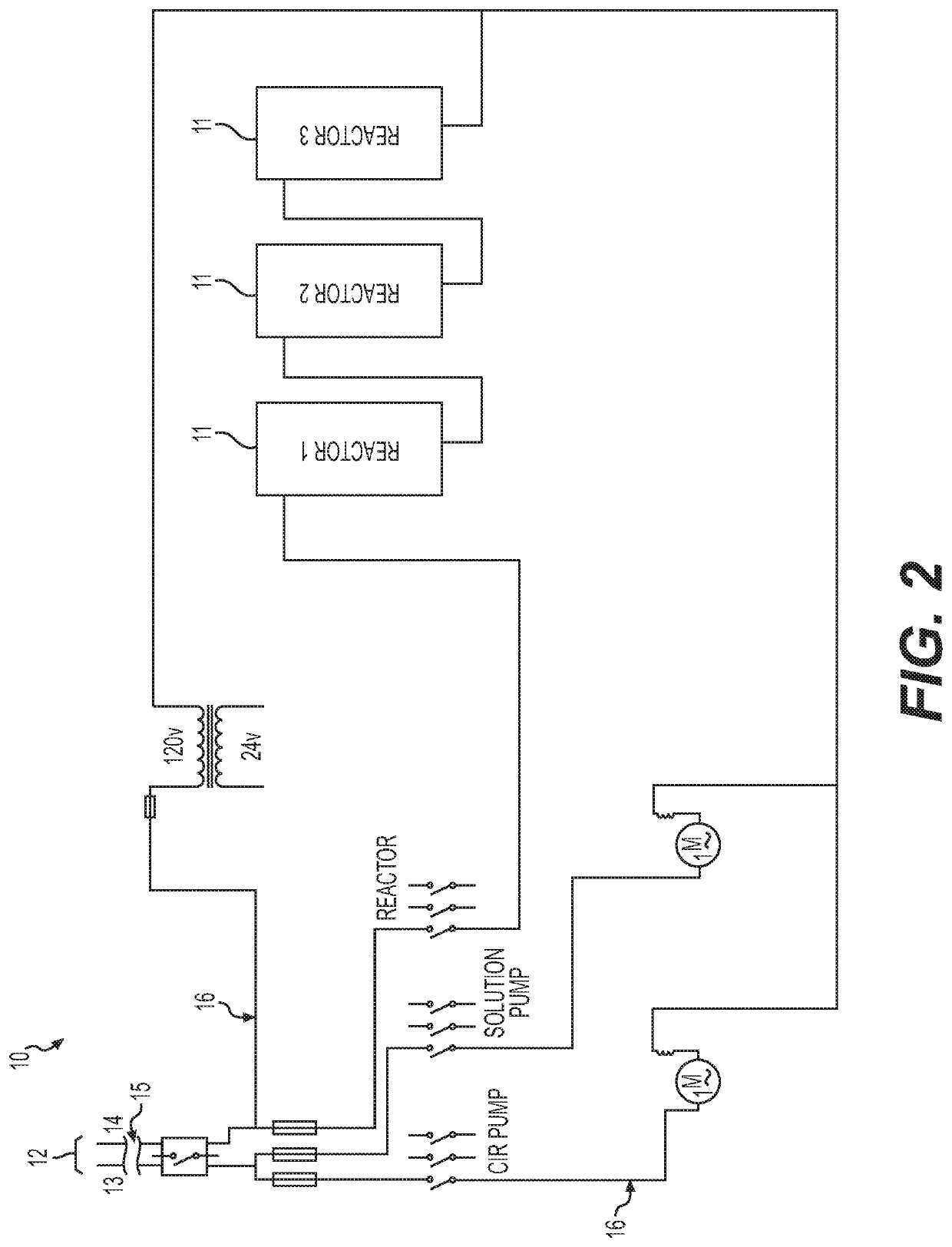
[0019]For a better understanding of the invention and its operation, turning now to the drawings, preferred resistance system 10 includes one or more reactor(s) 11 each including at least two electrodes 12, at least one of the electrodes 12 defined as cathode 13 and at least one of electrodes 12 defined as anode 14. The number of placement of electrodes 12 is not intended to be construed as a limitation on the present invention, as a range of electrode number and placement are within the scope of the instant disclosure, so long as the selected number and placement utilize spark gapping to aid in the manipulation of voltage and frequency to desired levels as it travels through the solution or substance. The size and shape of reactor(s) 11 are not intended as a limitation on the instant disclosure, as any geometry that retains substance or solution 15 in a closed or substantially closed system and that can modify the resistance experienced by the electrical current produced at electro...


PUM

PropertyMeasurementUnit
resistanceaaaaaaaaaa
electrical currentaaaaaaaaaa
currentaaaaaaaaaa

Abstract

The resistance method is a process for conditioning of an electric current and subjecting it to manipulated resistance levels to cause an effect on a substance as the current passes through. The method has two basic functions. One is to condition the electric current. This takes place during the series of steps that manipulate the frequency, voltage, and amps to provide a combination suitable for a predetermined threshold or action. The other is to manipulate the resistance of a substance. This is done by manipulating the atmospheric pressure, pH, salinity, and temperature of the substance, all of which takes place in a reactor. The reactor provides an isolated, enclosed environment for the manipulation to take place. The method also utilizes an electronic control system. The electronic control system simultaneously measures and manipulates the variables of the process, thereby creating an environment within the reactor that either increases or decreases the amount of resistance to which the electric current is subjected.

Description

FIELD OF THE INVENTION[0001]The invention herein pertains to electrical conditioning devices and methods, and particularly pertains to a method of conditioning the current and manipulating the resistance levels of an electrical current to achieve a desired result, including increasing the resistance in a closed system to create hot water or steam and decreasing the resistance in the same system to achieve a higher level of conductivityDESCRIPTION OF THE PRIOR ART AND OBJECTIVES OF THE INVENTION[0002]Electrical resistance produces heat when electrical current passes through a solution or substance. By conditioning the electrical current and manipulating the resistance levels of a solution or substance and / or the electrical current, a method can be generated to achieve a desired result. These results can vary from increasing the resistance the electrical current encounters to create hot water or steam to decreasing the resistance to promote a higher level of conductivity as defined by...

Claims


Application Information

Patent Timeline
Patent Type & Authority Patents(United States)
IPC IPC(8): H05B3/00H05B7/18B01J19/08C25B1/04C25B15/02F24H1/00
CPCB01J19/088C25B1/04F24H1/0018H05B3/0004C25B15/02H05B7/18F24H2250/02Y02E60/36
Inventor COBB, JR., JOHN ARTHUR
Owner COBB JR JOHN ARTHUR
Why Eureka
Try Eureka