
Milking system

a technology of milking system and vacuum system, which is applied in the direction of process and machine control, instruments, computer control, etc., can solve the problem of preventing the location of the vacuum transducer from being placed near the receiver, and achieve the effect of optimizing the milking system performance, reducing fluid flow restrictions, and improving vacuum system efficiency

Active Publication Date: 2020-01-28
GEHM LANNY +1
View PDF19 Cites 0 Cited by
  • Summary
  • Abstract
  • Description
  • Claims
  • Application Information

AI Technical Summary

Benefits of technology

[0013]An improved milking system is disclosed that optimizes milking system performance with features to reduce fluid flow restrictions and improve vacuum system efficiency. A method of incorporating a greater than atmospheric air pressure fresh air supply into the pulsation valve mechanism to improve pulsation function is disclosed with an optional method of limiting the total pressure within the pulsation chamber. This approach includes the use of a positive pressure air source having an inherent design limited maximum supply pressure with an example being a regenerative blower. The method is further improved by incorporating a means of automatically venting the positive pressure supply when pulsator demand for fresh air is reduced to prevent excess heating of the blower providing the fresh air. The method may be further improved with limited solenoid on time.
[0014]A method of delivering a more stable vacuum source to the teat end is disclosed with the addition of a vacuum controlled volume into the interconnecting path to the liner to provide a source of vacuum that bypasses the flow restrictions created by milk meters, milk sensors and other flow restricting features in the conventional system milk flow path. The added volume includes an inlet from the liner / cluster, an outlet to the collecting milk line and a new added inlet for an additional vacuum source for improved vacuum stability. The additional vacuum source has an optional feature for controlling and regulating the vacuum supply to the volume. The volume includes an option for preventing backflow of milk into the added vacuum source and an option for including a fresh air vent feature.
[0015]A method of improving vacuum regulation in milking facilities is disclosed where those facilities incorporate variable speed vacuum pump regulation. Typical conventional facilities utilize closed loop feedback of a measured vacuum level to continuously adjust vacuum pump speed for vacuum level regulation. Design limitations in some facilities, in particular rotary facilities, prevents the location of the vacuum transducer from being placed near the receiver and main milk lines. The disclosed invention incorporates a wireless method of transmitting vacuum level and provides further improvement with the addition of a mechanical regulator and an innovative vacuum pump speed control to provide improved vacuum regulation.
[0017]An improved multi-hose collection volume is disclosed for use on robotic milking systems. Robotic milking systems utilize one individual milk supply hose for each teat cup assembly. The individual hoses are joined in a collecting volume to merge the flow of milk from the individual teat cups. The innovation defines an improved volume to reduce vacuum fluctuations in the individual hoses caused by the flow of milking into the collecting volume. The collecting volume is further improved by incorporating an additional vacuum source that may also be regulated to control vacuum levels supplied. The volume provides a means of accepting fluid from multiple sources while preventing direct fluid flow from one source from flow over the entrance port of another source.

Problems solved by technology

Design limitations in some facilities, in particular rotary facilities, prevents the location of the vacuum transducer from being placed near the receiver and main milk lines.

Method used


Image

  • Milking system
  • Milking system
  • Milking system

Examples


Embodiment Construction

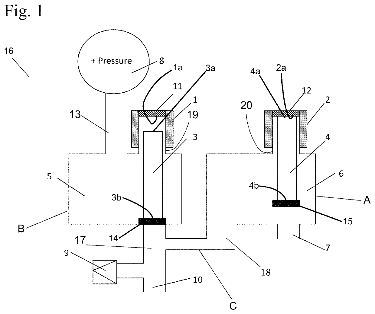
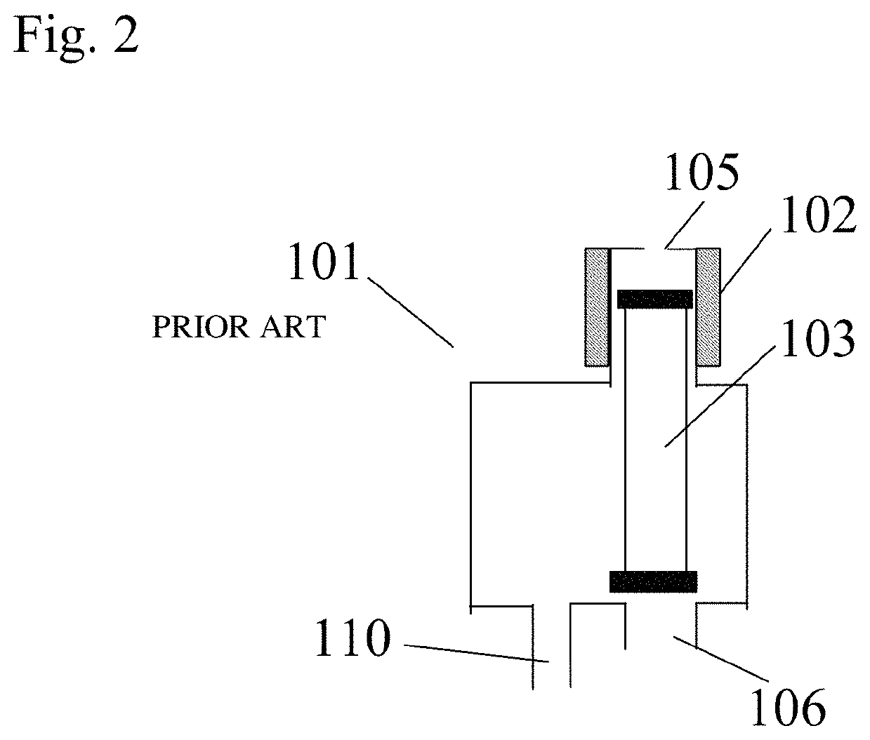
[0032]Referring to FIG. 1, a pulsator valving mechanism (16) used in the milking process of animals is shown. The basic design of this pulsator is described in U.S. Pat. No. 5,697,325. Prior art design pulsators, including the one described in U.S. Pat. No. 5,697,325, utilizes ambient air as the source of fresh air to provide pulsator output or common outlet (10) with atmospheric pressure air during the rest phase of the milking action. Prior art pulsators typically access atmospheric air directly through open ports in the pulsator or through connections to fresh air supply pipes having air filters incorporated to remove airborne debris.

[0033]It is desirable to provide a source of greater than atmospheric pressure air to the pulsator to ensure an adequate supply of fresh air within a filtered fresh air supply to the pulsator and to compensate for the large pressure drop between the pulsator and the cluster as the distance between the two becomes large. The greater than atmospheric p...


PUM


Abstract

Improving milking system performance through the incorporation of a source of greater than atmospheric pressure air into a pulsator while limiting total pressure in the teat cup. The system is further improved by providing an improved supply of regulated vacuum to the milking cluster throughout the milking process. The system is further improved with a monitoring and detecting the functional failure of the pulsation assemblies. Additional system improvements are provided with the addition of a fresh air valve assembly, a wireless method of regulating vacuum levels and the remote location of a pulsator assembly in a basement style parlor.

Description

FIELD OF THE INVENTION[0001]The present invention pertains to an improvement of a milking system for domesticated animals and, more particularly to a milking system which provides improved milking vacuum stability and liner action at the teat.DESCRIPTION OF RELATED ART[0002]Typical milking systems apply vacuum to the teat end combined with periodic alternating pressure to the teat cup of a milking apparatus. This results in the removal and the flow of milk from the udder and teat to which the teat cup is applied. Vacuum is supplied to the teat end through a series of interconnecting members such as pipes, meters, sensors and hoses that are connected between the liner and the vacuum pump. A means of regulating the system vacuum level is incorporated in the series of interconnecting members between the pump and the liner. The alternating pressure between the atmospheric pressure and vacuum cycles is controlled by a valving apparatus that feeds a pulsation chamber (volume between the l...

Claims


Application Information

Patent Timeline
Patent Type & Authority Patents(United States)
IPC IPC(8): A01J5/04A01J5/007A01J5/017A01J5/16G05B15/02G05D16/20F16K31/06
CPCG05D16/20A01J5/16A01J5/007A01J5/048A01J5/0175G05B15/02F16K31/06A01J5/14
Inventor GEHM, LANNYGEHM, WILLIAM
Owner GEHM LANNY
Learn More