
Dual integrated pump having a first and second pump portion connected in series and driven by a common shaft

a technology of integrated pumps and shafts, which is applied in the direction of rotary/oscillating piston pump components, machines/engines, liquid fuel engines, etc., can solve the problems of unreliable traditional mechanical seals and lip seals, cig pumps can have problems with cavitation, and cig pumps are often limited in speed or the height of fluid the cig pump can li

Active Publication Date: 2020-01-28
CIRCOR PUMPS NORTH AMERICA LLC
View PDF12 Cites 0 Cited by
  • Summary
  • Abstract
  • Description
  • Claims
  • Application Information

AI Technical Summary

Benefits of technology

The integrated system efficiently boosts inlet pressure, reduces cavitation, and maintains system efficiency by automatically adjusting pressure, while cooling the magnetic drive to prevent overheating, resulting in a more compact, cost-effective, and robust pumping solution.

Problems solved by technology

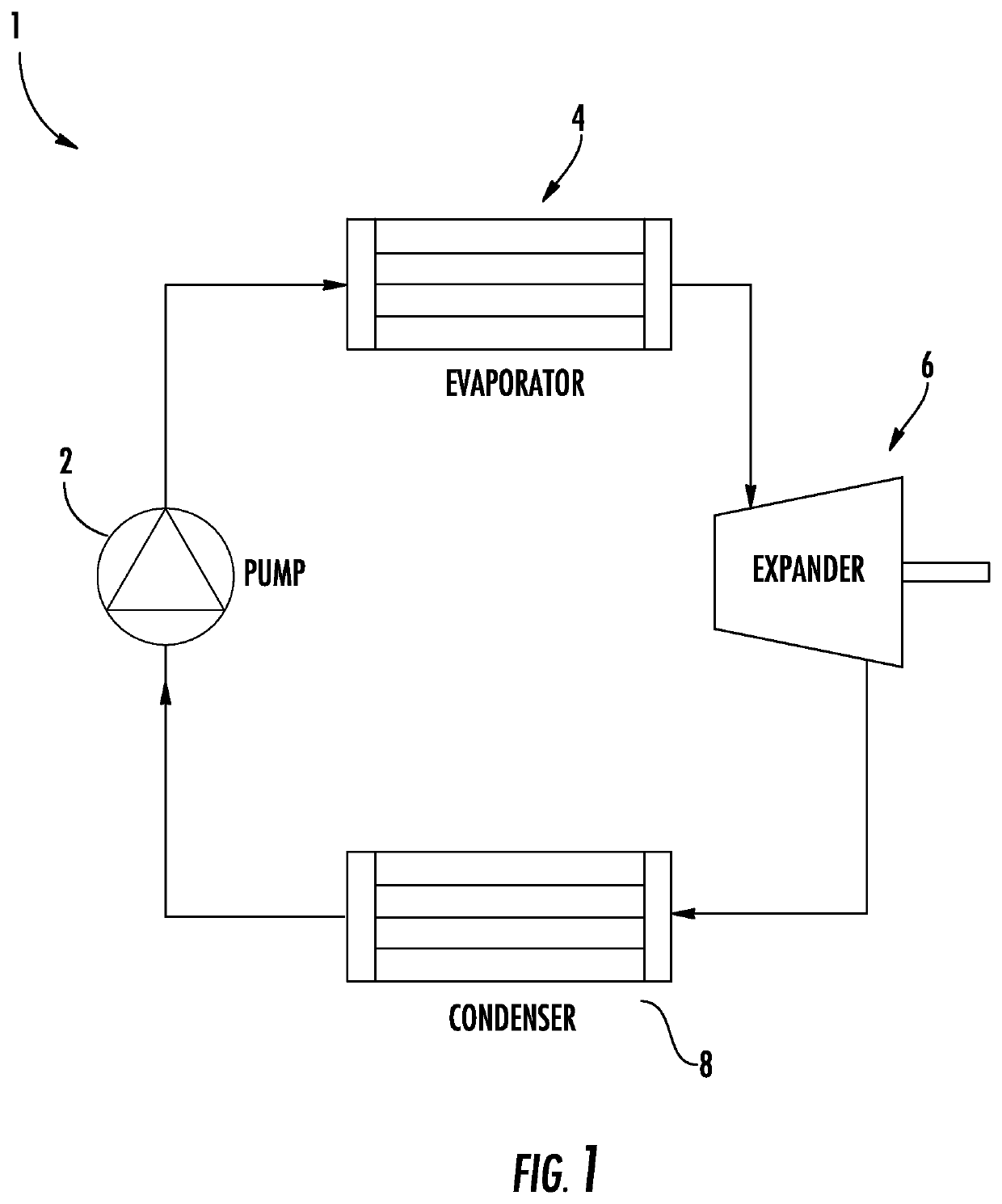
When pumping fluids with high vapor pressure, particularly refrigerants in Organic Rankine Cycles and refrigeration cycles, CIG (Crescent Internal Gear) pumps can have issues with cavitation caused by insufficient inlet pressure.
In order to meet pumping performance requirements these CIG pumps are often limited in speed or the height of fluid the CIG pump can lift.
Traditional mechanical seals and lip seals often are unreliable given the small amount of leakage that is allowed by governing agencies.
Magnetic drives operating at high speeds, however, come with another disadvantage, namely heat.
Heat is generated when using magnetic drives, and as this heat builds the drive becomes less efficient.
In some cases the heat generated by the drive offsets the advantage of the drive and can cause it to fail.
Often this is not enough, rendering the CIG pump insufficient for the application.

Method used


Image

  • Dual integrated pump having a first and second pump portion connected in series and driven by a common shaft
  • Dual integrated pump having a first and second pump portion connected in series and driven by a common shaft
  • Dual integrated pump having a first and second pump portion connected in series and driven by a common shaft

Examples


Embodiment Construction

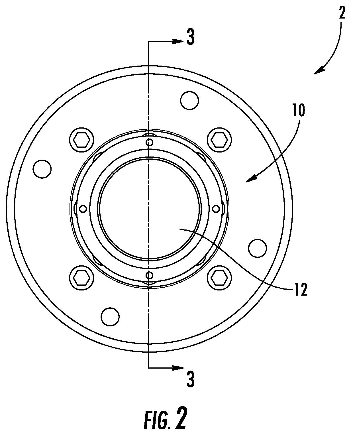
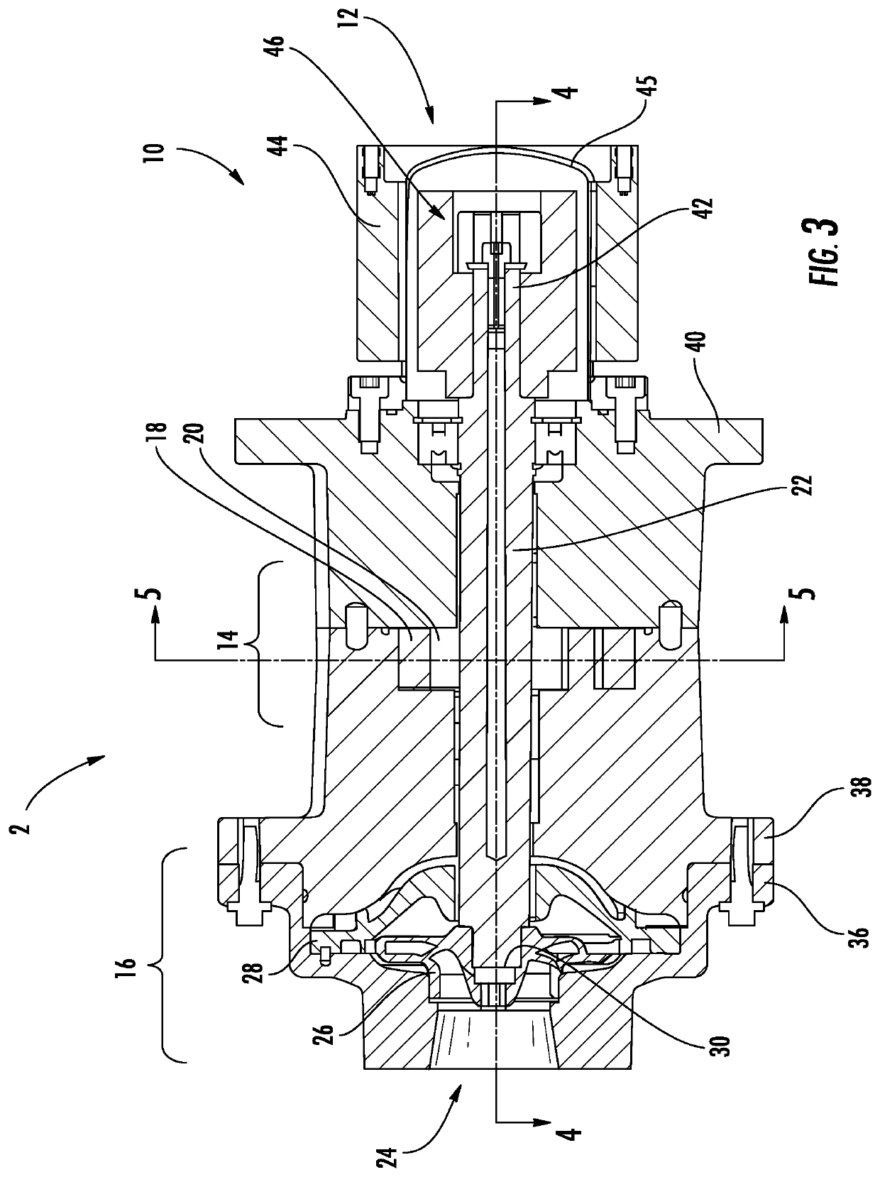
[0027]A pump is disclosed that incorporates a centrifugal boosting element and a CIG pump on a common shaft and within a common housing. The discharge passage for the centrifugal pumping element is common with the inlet passage for the CIG pump. The centrifugal element is configured so that pressure drop at the inlet to the centrifugal pump portion is minimal, thus reducing likelihood of cavitation of that portion. This provides a system designer with increased flexibility in determining where the unit can be mounted in the system and does not require the system designer to mount the CIG pump at the lowest point in the system. The fact that both pumping elements (i.e., centrifugal and CIG) are mounted on a common shaft reduces inefficiencies experienced with prior systems which use separate drivers for each pump. It also eliminates critical line losses associated with piping and piping bends between the boost pump and the CIG pump. Further, the common drive shaft provides an automat...


PUM


Abstract

A pump includes a housing, a drive shaft, a centrifugal pump portion having an impeller, and a gear pump portion having first and second gears. The impeller and one of the first and second gears are mounted to the drive shaft to drive the centrifugal pump portion and the gear pump portion at the same rotational speed. The gear pump can be a crescent internal gear (CIG) pump. The drive shaft can be rotated by a magnetic drive. The drive shaft can include a longitudinal bore in fluid communication with a cavity in the magnetic drive and with a discharge of the centrifugal pump portion to circulate working fluid through the magnetic drive to cool the drive. An impeller can be coupled to an inlet of the centrifugal pump portion.

Description

CROSS-REFERENCE TO RELATED APPLICATIONS[0001]The present application claims is a non-provisional of Provisional U.S. Pat. App. No. 62 / 032,848 by Duncan et al., titled “Dual Integrated Organic Working Fluid Pump,” filed on Aug. 4, 2014, the entirety of which is incorporated by reference herein.FIELD OF THE DISCLOSURE[0002]The disclosure generally relates to positive displacement pumps, and more particularly to an improved suction booster arrangement for a crescent internal gear pump.BACKGROUND OF THE DISCLOSURE[0003]When pumping fluids with high vapor pressure, particularly refrigerants in Organic Rankine Cycles and refrigeration cycles, CIG (Crescent Internal Gear) pumps can have issues with cavitation caused by insufficient inlet pressure. In order to meet pumping performance requirements these CIG pumps are often limited in speed or the height of fluid the CIG pump can lift. One solution is to boost the inlet pressure to the CIG pump so that it can operate without cavitation. Comm...

Claims


Application Information

Patent Timeline
Patent Type & Authority Patents(United States)
IPC IPC(8): F04D13/12F04C29/00F04C11/00F04C14/08F04C29/12F04C14/02F04D29/043F04D29/00F04D15/00F04C2/10F04C15/00F04C15/06F04D13/02F04D29/58F04D1/00
CPCF04C14/02F04C15/062F04C29/122F04D13/024F04C2/101F04C15/0069F04C29/0064F04D13/12F04C14/08F04D1/00F04D15/0066F04D29/5806F04D29/586F04C11/006F04D29/043F04D29/007F04C2240/603
Inventor DUNCAN, PATRICK WILSONALEXANDER, PHILIP TAYLORHINCKLEY, CHARLES
Owner CIRCOR PUMPS NORTH AMERICA LLC
Learn More