

Implantable device and delivery system for reshaping a heart valve annulus
a technology of implantable devices and delivery systems, which is applied in the field of implantable medical devices, can solve the problems of excessive dilatation of the annulus of the mitral heart valve, serious problems in the operation of the heart valve, and the expansion and weakening of the heart chamber, so as to reduce the risk of anchor fatigue failure, reduce the size of the dilated annulus, and improve the effect of the effect of the ring-like member
- Summary
- Abstract
- Description
- Claims
- Application Information
AI Technical Summary
Benefits of technology
Problems solved by technology
Method used
Image

Examples
Embodiment Construction
, ” one will understand how the features of the embodiments described herein provide advantages over existing systems, devices and methods.
[0011]The following disclosure describes non-limiting examples of some embodiments. For instance, other embodiments of the disclosed systems and methods may or may not include the features described herein. Moreover, disclosed advantages and benefits can apply only to certain embodiments of the invention and should not be used to limit the disclosure.
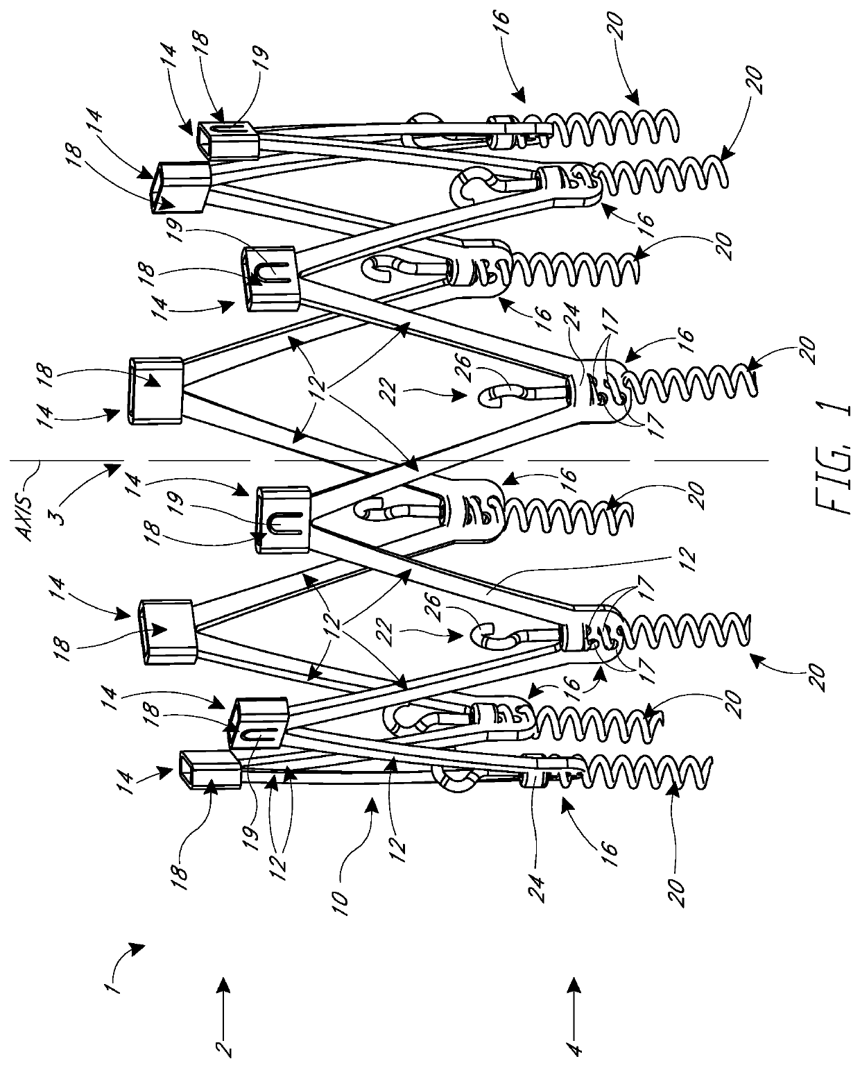
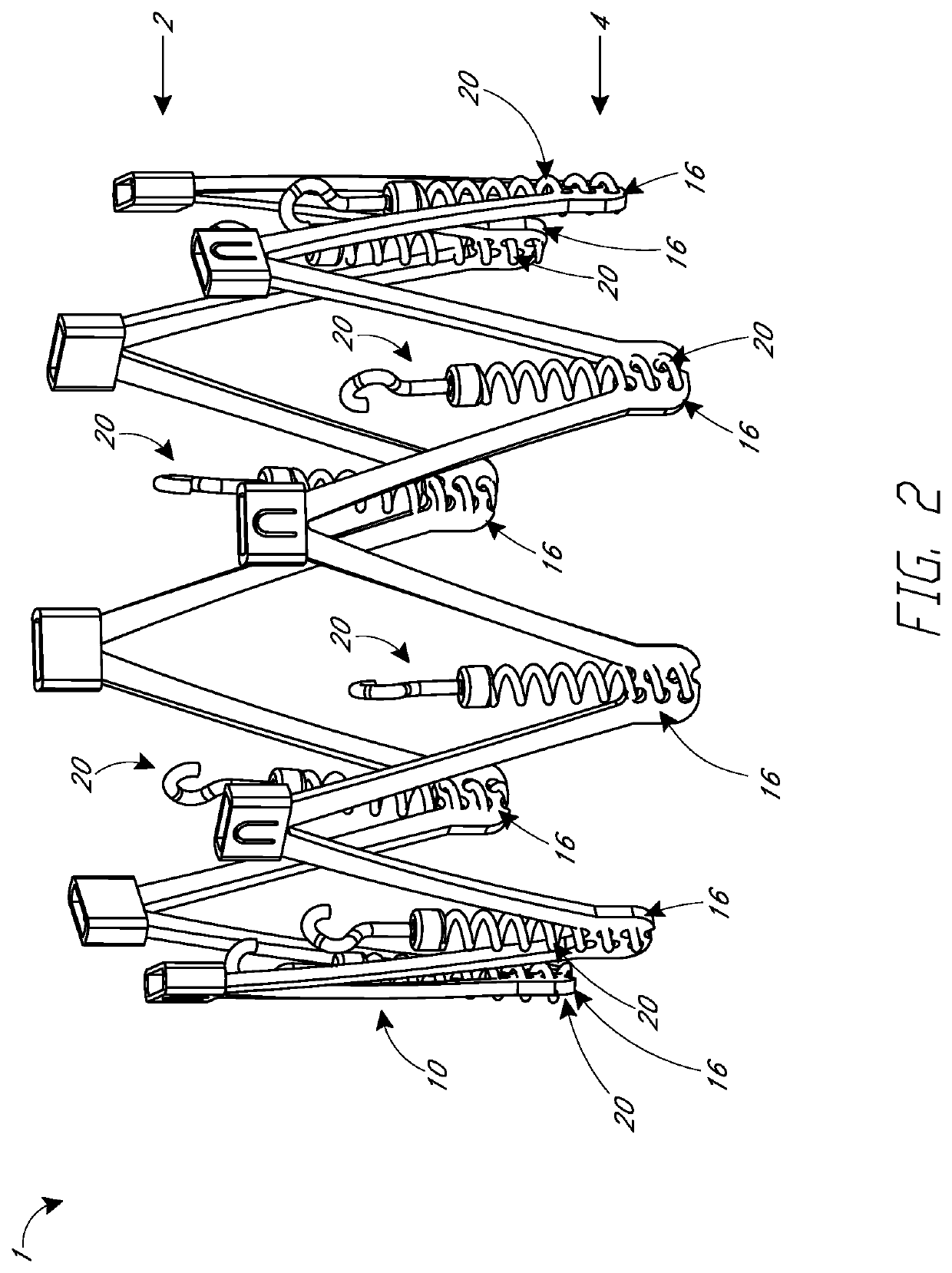
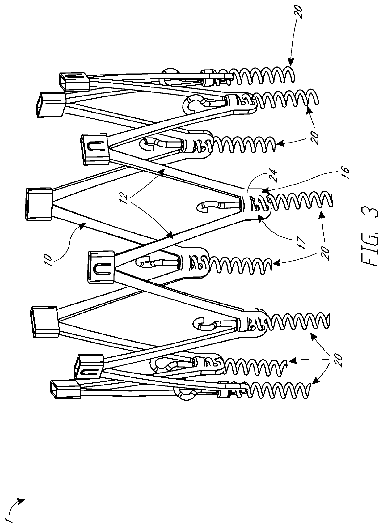
[0012]Systems, devices and methods for a heart valve implant and related delivery systems are described. The implant is intended to be delivered in a minimally invasive percutaneous manner, such as transfemorally, transeptally, or transapically. The implant may instead be implanted surgically, in that it should reduce the duration of the procedure and, more particularly, the duration that the patient is on bypass. The development can be directed to mitral valve or tricuspid valve procedures.
[0013]The...
PUM
 Abstract
Description
Claims
Application Information