Liquid pump with cavitation mitigation

a liquid pump and cavitation mitigation technology, applied in the direction of machines/engines, liquid fuel engines, positive displacement liquid engines, etc., can solve the problems of cavitation erosion, cavitation erosion at undesirable locations, and pump performance can be undermined

Active Publication Date: 2020-02-11
CATERPILLAR INC
View PDF16 Cites 10 Cited by
  • Summary
  • Abstract
  • Description
  • Claims
  • Application Information

AI Technical Summary

Problems solved by technology

When the cavitation bubbles collapse adjacent a surface, cavitation erosion can occur.
In some instances, cavitation erosion can occur at undesirable locations, such as the inlet port passage or in the vicinity of valve seats.
Depending upon where the cavitation damage occurs, and the extent of that damage, the pump performance can be undermined, and maybe more importantly, the eroded particles can find their way into fuel injectors possibly causing even more serious problems.
A flow pattern is apparently formed by the valve in a way that encourages cavitation bubble collapse away from surfaces that could result in unacceptable cavitation damage to the pump.

Method used


Image

  • Liquid pump with cavitation mitigation
  • Liquid pump with cavitation mitigation
  • Liquid pump with cavitation mitigation

Examples


Embodiment Construction

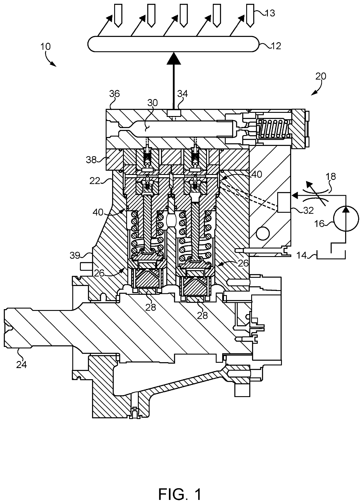
[0015]Referring to FIG. 1, there is shown a liquid system 10, such as a fuel system for an internal combustion engine. Liquid system 10 (hereinafter “system 10”) may include a reservoir 12 for containing a pressurized fluid, such as a common rail or the like (hereinafter “common rail 12”) that is structured to contain pressurized fluid and to feed pressurized fluid to a plurality of fluid delivery devices or fuel injectors 13. Liquid system 10 may include a fuel system structured for use in a direct injection compression ignition diesel engine, for example, where fuel injectors 13 are each positioned at least partially within an engine cylinder. Common rail 12 could include a single-bore, elongated pressure vessel, for example, or a plurality of separate fluid pressure accumulators coupled together in a so-called daisy chain arrangement, or still another configuration. System 10 also includes a liquid supply such as a fuel tank 14, and a low-pressure transfer pump 16 coupled with fu...


PUM


Abstract

A liquid pump applicable in a fuel system such as a common rail fuel system includes a valve assembly having a valve stack with axially aligned components, dead volume, and vapor-distributing flow channels, for cavitation mitigation. An inlet valve meters a flow of liquid into the pump for pressurization by a plurality of reciprocating plungers operated by way of a rotating camshaft.

Description

TECHNICAL FIELD[0001]The present disclosure relates generally to inlet metered liquid pumps with output control via an inlet throttle valve, and more particularly to an inlet metered liquid pump having a valve stack designed for cavitation mitigation.BACKGROUND[0002]In one class of high pressure liquid pumps, output from the pump is controlled by throttling the inlet with an electronically controlled metering valve. As a consequence, cavitation bubbles are generated when the output of the pump is controlled to be less than the volume displaced with each reciprocation of the pump plunger. One application for such a pump is in a fuel system that utilizes a common rail and a high-pressure fuel pump to pressurize the rail. In this specific example, the pump is driven directly by the engine, and the output from the pump is controlled by changing the inlet flow area via the inlet throttle valve.[0003]When the inlet throttle valve reduces the flow area to the plunger cavity, cavitation bub...

Claims


Application Information

Patent Timeline
Patent Type & Authority Patents(United States)
IPC IPC(8): F02M59/46F02M59/02F02M59/10F04B11/00F04B49/22F02M59/34F02M59/16
CPCF02M59/34F04B49/225F02M59/102F04B11/0091F02M59/02F02M59/022F02M59/464F02M59/462F02M2200/04F02M59/16F04B53/10F04B17/05F04B49/03F02M63/0078F02M2200/40
Inventor STECKLEIN, ADAMCARLSON, JOSHUAWARNE, DERIKPARANJAPE, RAJESHIBRAHIM, DANIELCOX, GLENNLI, ZHENYUHINRICHSEN, RYAN
Owner CATERPILLAR INC
Why Eureka
Try Eureka