Torque sensor for detecting occurrence of metal fatigue in an elastic body

a technology of torque sensor and metal fatigue, which is applied in the direction of force/torque/work measurement apparatus, instruments, measurement devices, etc., can solve the problems of metal fatigue and elastic body may eventually break, and achieve the effect of reliable detection of metal fatigue, stably providing the first electric signal, and large spring constant more slowly

Active Publication Date: 2020-02-11
TRI FORCE MANAGEMENT CORP
View PDF15 Cites 0 Cited by
  • Summary
  • Abstract
  • Description
  • Claims
  • Application Information

AI Technical Summary

Benefits of technology

[0018]In this case, the effective opposing area of each pair of electrodes forming the first and second capacitive elements does not change even when the torque around the Z axis acts, and thus, it is possible to improve accuracy in torque detection and accuracy in determination on whether the torque sensor functions normally.
[0071]Alternatively, the acting torque may be measured based on the second electric signal. In this case, the first and second deformation portions of the detection portion corresponding to the capacitive element that provides the second electric signal have the relatively small spring constant, and thus, are subjected to relatively large displacement (have a high sensitivity) with respect to the acting torque, thereby enabling the torque measurement with an excellent S / N.

Problems solved by technology

However, a current capacitance type torque sensor is provided with a mechanism including a torque detection portion, a CV conversion circuit, and an electronic circuit including a microcomputer, for example, and is likely to malfunction due to condensation, an impact, an overload, or a contamination that is mixed between a pair of parallel flat plates to provide the capacitance.
In particular, a torque detection portion of the torque sensor has flexibility, and thus, metal fatigue is caused by the overload or a repeated load.
As a result, a crack or the like may be generated in an elastic body forming the torque detection portion, and there is a risk that the elastic body may be eventually broken.

Method used


Image

  • Torque sensor for detecting occurrence of metal fatigue in an elastic body
  • Torque sensor for detecting occurrence of metal fatigue in an elastic body
  • Torque sensor for detecting occurrence of metal fatigue in an elastic body

Examples


Embodiment Construction

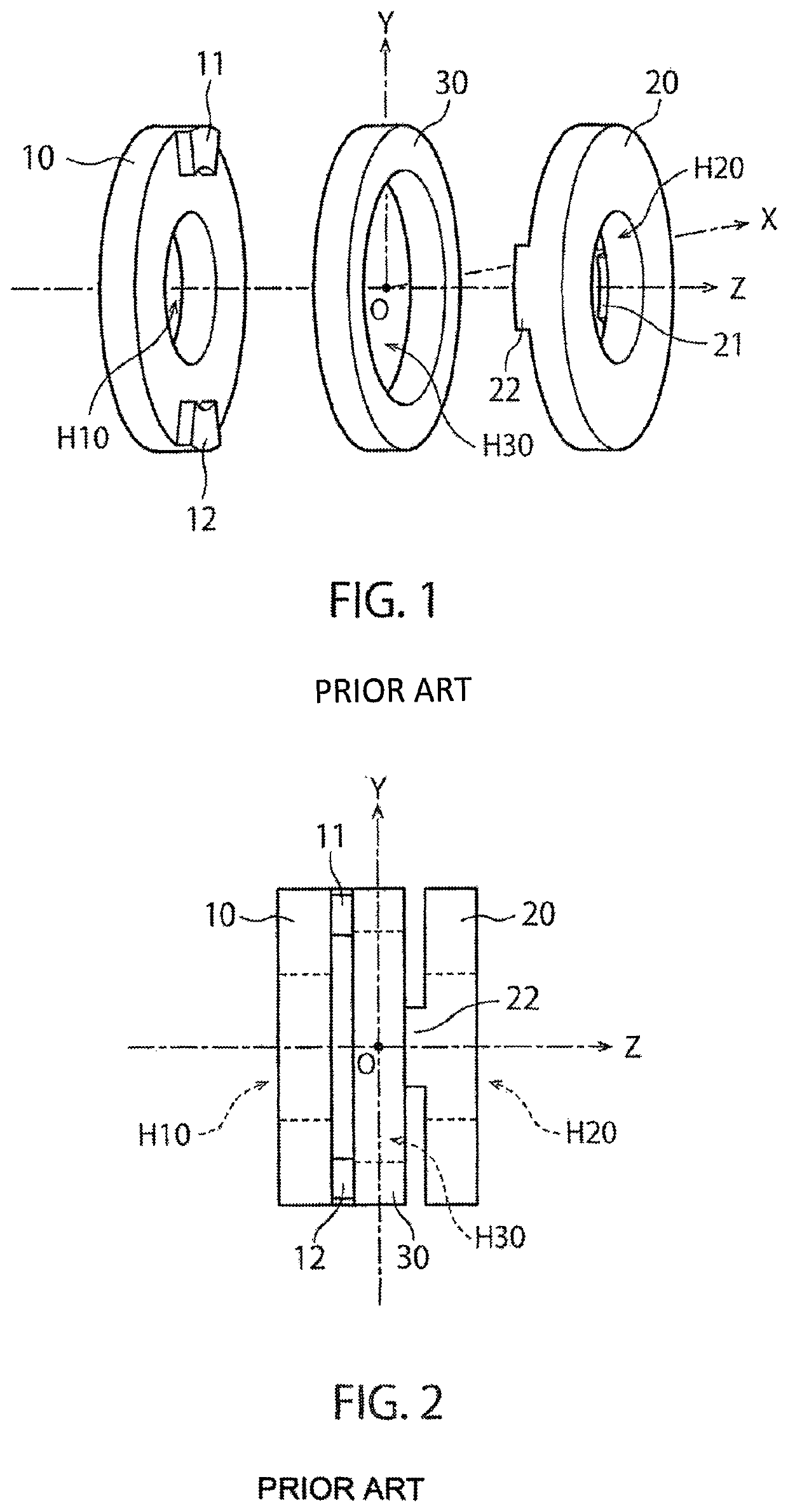
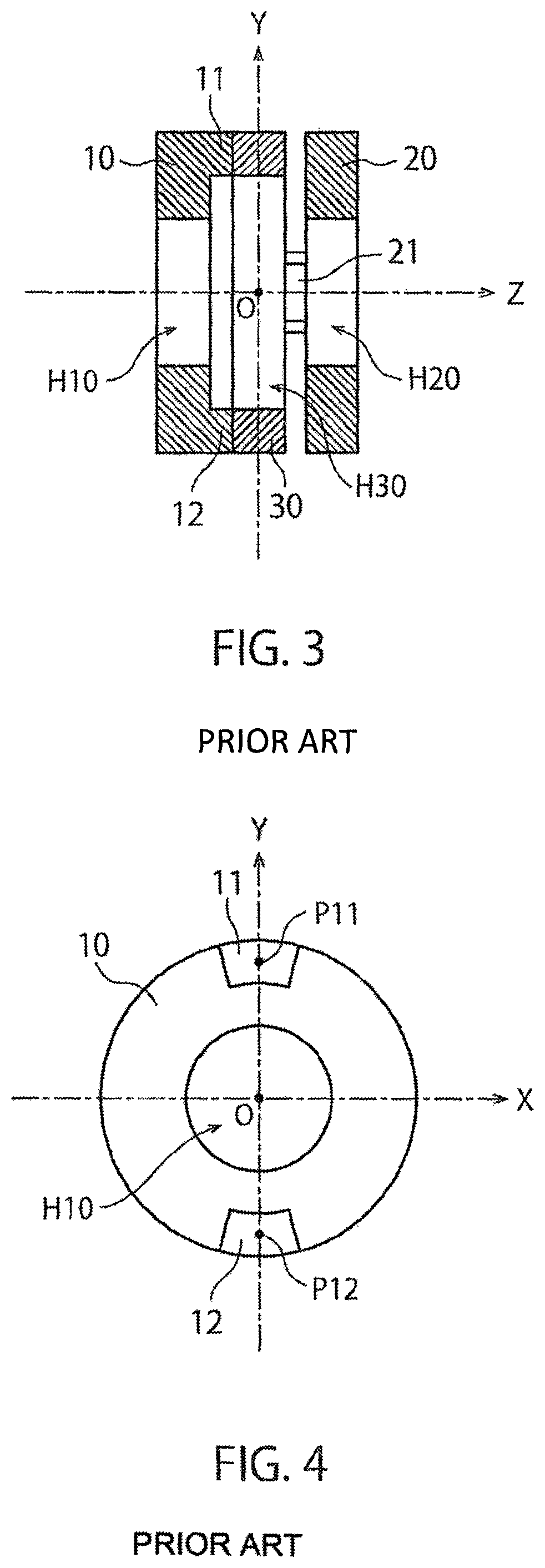
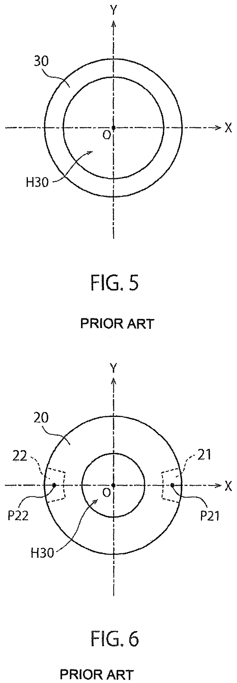
[0117]Since own principle of torque detection used in a torque sensor according to the present invention is common to the conventional torque sensor, firstly, a structure of the conventional torque sensor and the principle of torque detection will be described in § 1 to § 3. In addition, an embodiment of a torque sensor according to the present invention will be described in § 4 to § 6 based on this description. In addition, a structure of a torque sensor adopting a detection portion of a waveform and a torque detection principle thereof will be described in § 7 and § 8 as another example, and the embodiment of the torque sensor according to the present invention adopting a detection portion of a waveform will be described in § 9 to § 11. The torque sensor adopting the waveform detection portion described in § 7 and § 8 is proposed in International Patent Application PCT / JP2015 / 052783 filed by the present applicant. In addition, a modified example applicable to any embodiment will b...


PUM

PropertyMeasurementUnit
angleaaaaaaaaaa
angleaaaaaaaaaa
angleaaaaaaaaaa

Abstract

A torque sensor includes: an annular deformation body; first and second displacement electrodes which cause displacement by elastic deformation of the annular deformation body; first and second fixed electrodes arranged at positions opposite the first and second displacement electrodes; and a detection circuit that outputs an electric signal indicating a torque based on a variation amount of capacitance values of first and second capacitive elements each of which is configured of the displacement electrode and the fixed electrode. The annular deformation body includes a high elastic portion and a low elastic portion having a spring constant smaller than a spring constant of the high elastic portion. The detection circuit determines whether the torque sensor functions normally based on a ratio between first and second electric signals.

Description

RELATED APPLICATION[0001]This application is an application under 35 U.S.C. 371 of International Application No. PCT / JP2016 / 071307 filed on Jul. 20, 2016, the entire contents of which are incorporated herein by reference.TECHNICAL FIELD[0002]The present invention relates to a torque sensor, and particularly to a sensor having a function of outputting a torque acting around a predetermined rotation axis as an electric signal.BACKGROUND ART[0003]Torque sensors configured to detect a torque acting around a predetermined rotation axis have been widely used for a variety of transport machinery and industrial machinery. For example, the following Patent Literature 1 discloses a torque sensor of a type in which mechanical deformation caused by action of a torque is detected by a strain gauge. In addition, Patent Literature 2 discloses a sensor which detects a torque acting on a shaft by forming a magnetostrictive film through plating on a shaft surface and measuring a change in magnetic pr...

Claims


Application Information

Patent Timeline
Patent Type & Authority Patents(United States)
IPC IPC(8): G01L5/22G01L25/00G01L3/14G01L3/10
CPCG01L25/003G01L3/1442G01L3/106G01L5/226
Inventor OKADA, KAZUHIROOKADA, MIHO
Owner TRI FORCE MANAGEMENT CORP
Why Eureka
Try Eureka